DEWALT 14000 Generator 3
Portability Kit Installation
Tools Required:
• 1/2” wrench
• 1/2” and 9/16” sockets and ratchets
• 10 mm socket or wrench
• wood blocks
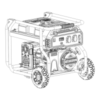
Refer to the drawing for proper alignment of foot bracket
and wheel brackets.
Wheel Bracket & Wheel Installation
1. Block up end of generator about 8” high, opposite fuel tank
cap to install wheels and wheel bracket assembly.
2. Add 5/16 washer (item 29) to the 5/16” x 2” bolts (item 71)
and insert bolts/washers through holes located in base pan
of carrier.
3. Place wheel bracket (item 65) through bolts and add a 5/16
nyloc nut (item 27). Tighten securely. (On bottom side of
pan in-between the holes will be a 1” square brace. The
wheel bracket will set on this brace.)
4. Add wheel spacer (item 70) to axle.
5. Slide wheel (item 64) onto axle until snug against spacer.
The wheel is on correctly if there is approximately a 1/2”
gap between the carrier tubing and the side of the wheel. If
it is less then 1/2” from the carrier, turn wheel over to install.
Align wheels parallel to carrier tubing and tighten nuts
securely. To align correctly, the bolts holding the wheel
bracket may have to be loosened.
6. Add 5/8 washer (item 95) and cotter pin (item 69) on end of
axle.
7. Repeat instructions for remaining wheel.
Foot Bracket Installation
1. Block up opposite end of unit about 8” high.
2. Loosen M6 x 20 screws (item 75) as needed to allow clear-
ance for installation.
3. Add 5/16 washer (item 29) to 5/16” x 1” bolts (item 30) and
place through holes in base pan.
4. Add foot bracket assembly (item 66) to bolts. Add 5/16
nyloc nuts (item 27) and tighten securely.
5. Repeat instructions for remaining foot bracket assembly.
6. Tighten M6 x 20 screws securely.
Handle Installation
1. Place handle (item 53) on carrier on same end as foot
bracket as shown in the diagram.
2. Slide 3/8 x 1.75” bolts (item 56) and 3/8 washers (item 96)
through handle and handle bracket. Secure with 3/8” nyloc
nuts (item 97). Tighten handle securely.
3. Apply aerosol hairspray or similar adhesive to handle. Slide
handle grips (item 55) onto handle. The aerosol hairspray
allows easier assembly and adheres the grip to the handle.
4. Insert caps (item 98) into end of handle.
Locking Handle
1. Attach the lanyard (item 52) to release pin (item 28) and
carrier as shown in illustration.
2. To lock the handle in the extended position, align holes in
the handle brackets with holes in the carrier brackets. Insert
release pin.
98
52
26
30
96
56
28
55
64
69
29
75
27
70
65
27
67
66
12
75
96
97
53
29
71
95

 Loading...