32
ENGLISH
Top Handle (Fig.A)
A fixed top handle
4
is provided for carrying the tool and for
use as an additionalhandle.
E-Clutch® System (Fig.A)
Your joist drill is equipped with the DeWALT anti‑rotation
E‑Clutch® System. This feature senses the motion of the tool
and shuts the tool down if necessary. The red LED indicator
illuminates when the E‑Clutch® System
9
isengaged.
INDICATOR DIAGNOSIS SOLUTION
OFF Tool is functioning
normally
Follow all warnings and instructions
when operating the tool.
SOLID E‑Clutch® System
has been activated
(ENGAGED)
With the tool properly supported,
release trigger. The tool will function
normally when the trigger is
depressed again and the indicator
light will go out.
Torque
WARNING: This is a high-torque drill. To reduce the risk of
serious personal injury, ALWAYS hold tool firmly with both
hands in the proper position for operation asshown.
Torque is the twisting action the drill produces in regards to
the rotating bit. As the drill bit meets resistance in the material
being drilled, the motor responds by adjusting the output
torque to meet the requirement up to the maximum capacity of
the motor and gearsystem.
Bracing the Tool (Fig.C, D)
WARNING: To reduce the risk of serious personal injury,
NEVER brace the tool against the batterypack.
The bit rotates clockwise when the tool is in the forward
position and counterclockwise when the tool is in the
reverseposition.
ASSEMBLY AND ADJUSTMENTS
WARNING: To reduce the risk of serious personal
injury, turn tool off and disconnect battery pack
before making any adjustments or removing/
installing attachments or accessories. An accidental
start-up can causeinjury.
WARNING: Use only DeWALT batteries andchargers.
Description (Fig.A, B, E)
WARNING: Never modify the power tool or any part of it.
Damage or personal injury couldresult.
1
Battery pack
2
Battery release button
3
Main handle
4
Top handle
5
Variable speed trigger
6
Worklight
7
Forward/reverse button
8
1/2" (13mm) Keyed chuck
9
E‑Clutch® system indicator
10
Chuck collar
11
Chuck key
12
Retention clip
13
Key handle
14
Date code
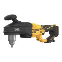
Intended Use
The DCD444 compact stud and joist drill is designed for
professional drilling at various work sites (i.e., constructionsites).
Do not use under wet conditions or in the presence of
flammable liquids orgases.
These compact stud and joist drills are professional powertools.
Do not let children come into contact with the tool. Supervision
is required when inexperienced operators use thistool.
• Young children and the infirm. This appliance is not
intended for use by young children or infirm persons
withoutsupervision.
• This product is not intended for use by persons (including
children) suffering from diminished physical, sensory or
mental abilities; lack of experience, knowledge or skills
unless they are supervised by a person responsible for their
safety. Children should never be left alone with thisproduct.
Date Code Position (Fig.A)
The date code
14
, which also includes the year of manufacture,
is printed into thehousing.
Example:
2022XX XX
Year and Week of Manufacture
Markings on Tool
The following pictograms are shown on the tool:
a
Read instruction manual beforeuse.
g
Wear earprotection.
f
Wear eyeprotection.
n
Visible radiation. Do not stare intolight.
Variable Speed Trigger (Fig.A)
Depressing the variable speed trigger
5
turns the tool on,
releasing the variable speed trigger turns the tool off. The
variable speed trigger permits speed control—the farther the
trigger is depressed, the higher the speed of thedrill.
Forward/Reverse Button (Fig.A)
A forward/reverse button
7
determines the direction of the
tool. It is located in front of the variable speedtrigger
5
.
To select forward rotation, release the variable speed trigger and
depress the forward/reverse button on the right side of thetool.
To select reverse, depress the forward/reverse button on the left
side of the tool. When changing the position of the forward/
reverse button, be sure the variable speed trigger isreleased.
The centre position of the forward/reverse control button locks
the tool in the off position. When changing the position of the
forward/reverse control button, be sure the variable speed
trigger isreleased.
 Loading...