37
ENGLISH
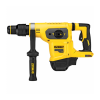
Performing an Application (Fig.A)
WARNING: TO REDUCE THE RISK OF PERSONAL
INJURY, ALWAYS ensure workpiece is anchored or
clamped firmly. If drilling thin material, use a wood
“back-up” block to prevent damage to thematerial.
WARNING: Always wait until the motor has come to
a complete standstill before changing the direction
ofrotation.
1. Choose and install the appropriate chuck, adapter, and/or
bit onto the tool. Refer to Bit and BitHolder.
2. Using the mode selector dial
3
, selectthe mode
appropriate to desired application. Refer to
OperationModes.
3. Adjust the side handle
5
asnecessary.
4. Select the direction ofrotation using the forward/reverse
control button
2
. When changing the position of the
control button, be sure the trigger isreleased.
Operation Modes (Fig.A)
WARNING: Do not select the operating mode when the
tool isrunning.
Your tool is equipped with a mode selector dial
3
to selectthe
mode appropriate for the desiredoperation.
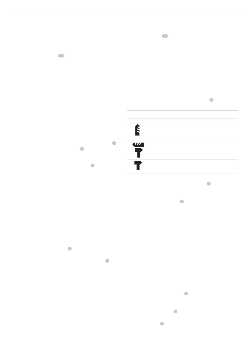
Symbol Mode Application
Rotary Drilling
Screwdriving
Drilling into steel, wood
andplastics
Rotary
Hammering
Drilling into concrete and
masonry
Hammering
only
Lightchipping
To select an operating mode:
1. Depress the mode selector release button
4
.
2. Rotate the mode selector dial so that the arrow points to the
symbol corresponding with the desiredmode.
NOTE: The mode selector dial
3
must be in rotary drilling,
rotary hammering or hammering only mode at all times. There
are no operable positions in between. It may be necessary to
briefly run the motor after having changed from 'hammering
only' to 'rotary' modes in order to align thegears.
Worklight (Fig.A)
CAUTION: Do not stare into worklight. Serious eye
injury couldresult.
There is a worklight
13
located on the front of the tool. The
worklight is activated when the trigger switch is depressed, and
will automatically turn off 20seconds after the trigger switch is
released. If the trigger switch remains depressed, the worklight
will remainon.
NOTE: The worklight is for lighting the immediate work surface
and is not intended to be used as aflashlight.
Forward/Reverse Control Button (Fig.A)
A forward/reverse control button
2
determines the direction of
bit rotation and also serves as a lock-offbutton.
To select forward rotation, release the trigger switch
1
and
depress the forward/reverse control button on the right side of
thetool.
To select reverse, depress the forward/reverse control button
on the left side of thetool.
The centre position of the control button locks the tool in
the off position. When changing the position of the control
button, be sure the trigger isreleased.
NOTE: The first time the tool is run after changing the direction
of rotation, you may hear a click on start-up. This is normal and
does not indicate aproblem.
Trigger Switch (Fig.A)
To turn the tool on, squeeze the trigger switch
3
. To turn the
tool off, release the trigger switch. Your tool is equipped with
a brake. The chuck will stop as soon as the trigger switch is
fullyreleased.
Variable Speed Trigger Switch
The variable speed trigger switch enables you to select the best
speed for a particular application. The farther you squeeze the
trigger switch, the faster the tool will operate. For maximum
tool life, use variable speed only for starting holes orfasteners.
NOTE: Continuous use in variable speed range is not
recommended. It may damage the trigger switch and should
beavoided.
Proper Hand Position (Fig.A,E)
WARNING: To reduce the risk of serious personal injury,
ALWAYS use proper hand position asshown.
WARNING: To reduce the risk of serious personal
injury, ALWAYS hold securely in anticipation of a
suddenreaction.
Proper hand position requires one hand on the side handle
5
,
with the other hand on the main handle
8
.
Active Vibration Control (AVC) System (Fig. A)
For best vibration control, hold the tool as described in Proper
Hand Position and apply just enough pressure so the damping
device on the main handle is approximately midstroke.
The active vibration control
16
neutralises rebound vibration
from the hammer mechanism. Lowering hand and arm
vibration, it allows more comfortable use for longer periods of
time and extends the life of theunit.
The hammer only needs enough pressure to engage the active
vibration control. Applying too much pressure will not make
the tool drill or chip faster and active vibration control will
notengage.
installing attachments or accessories. An accidental
start-up can causeinjury.