12
DANSK
Indstilling af skoen i smig (Fig. E)
Sådan stilles skoen i smig
1. Fjern støvopsamlingstilbehøret, hvis det er monteret
på værktøjet, da værktøjet ikke stilles i smig, hvis det er
påmonteret. Se afsnittetStøvopsamling.
2. Lås skoen op ved at trække greb til sålskråsnit
8
tilsiden.
Installation og demontering af klingen
(Fig.D, J)
Sådan installeres en klinge
BEMÆRK: Denne stiksav bruger kun stiksavklinger med T-skaft.
BEMÆRK: DT2074 skæreklinger i samme niveau er kun til brug
sammen med DeWALT DCS334 og DCS335stiksave.
BEMÆRK: Ved installation af skæreklinger i samme niveau
(DT2074) skal antisplintindsatsen (
20
, Fig. J) fjernes, og skoen
skal blive i 0° positivstopposition.
BEMÆRK: Den korrekte savklinge skal vælges til det materiale,
dersaves.
1. Hold klingeudløserlåsen
4
åben, som vist på FigurD.
2. Indsæt T-skafteklingen i skruetvingemekanismen
13
, mens
klingens bagside ledes ind i rillen på styrevalserne
14
.
3. T-skaftet skal være helt inde iskruetvingemekanismen.
4. Slipklingeudløserlåsen.
Sådan fjernes en klinge
FORSIGTIG: Rør ikke ved brugte klinger, de kan være
varme. Det kan resultere ipersonskade.
1. Hold klingeudløserlåsen
4
åben.
2. Klingen vil falde ud, når den ryster denlet.
3. Slipklingeudløserlåsen.
2. Skub den ind i håndtaget, indtil batteripakken sidder godt
fast i værktøjet og kontrollér, at den ikke river sigløs.
Sådan fjernes batteripakken fra værktøjet
1. Tryk på udløserknappen
12
og træk batteripakken ud fra
værktøjetshåndtag.
2. Isæt batteripakken i opladeren som beskrevet i
opladerafsnittet i dennevejledning.
Batteripakker til brændstofmåler (Fig. C)
Nogle DeWALT batteripakker indeholder en brændstofmåler,
som består af tre grønne LED lys, som angiver niveauet for den
resterende opladning ibatteripakken.
Du aktiverer brændstofmåleren ved at trykke på og holde
brændstofmålerknappen
16
nede. En kombination af de tre
grønne LED lys vil lyse og angive niveauet for den resterende
opladning. Når niveauet for opladning i batteriet ligger under
den brugbare grænse, lyser brændstofmåleren ikke, og batteriet
skalgenoplades.
BEMÆRK: Brændstofmåleren giver kun en indikation af den
opladning, der resterer i batteripakken. Den angiver ikke
værktøjets funktionalitet og er underlagt variation baseret på
produktkomponenter, temperatur ogslutbrugeranvendelse.
Indsættelse og fjernelse af batteripakken
fra værktøjet (Fig. C)
BEMÆRK: For de bedste resultater kontrollér at
batteripakken
11
er fuldtopladet.
Sådan installeres batteripakken i værktøjets
håndtag
1. Ret batteripakken
11
ind efter rillerne inde i håndtaget
(Fig.C).
SAMLING OG JUSTERING
ADVARSEL: For at reducere risikoen for personskade,
sluk og tag batteripakken af, inden der foretages
justeringer eller afmontering/installation af udstyr
eller tilbehør. Utilsigtet start kan medførekvæstelser.
ADVARSEL: Anvend kun DeWALT‑batteripakker og
‑opladere.
Beskrivelse (Fig.A)
ADVARSEL: Modificér aldrig elektrisk værktøj eller nogen
dele deraf. Det kan medføre materiale‑ ellerpersonskade.
1
Hastighedsudløser (DCS334), tænd/sluk-kontakt (DCS335)
2
Startspærreknap (kun DCS334)
3
Hastighedskontrolviser
4
Klingeudløserlås
5
Fingerbeskyttelsesskærm
6
Pendulfunktionsgreb
7
Sko
8
Greb til sålskråsnit
9
Håndtag
10
Datokode
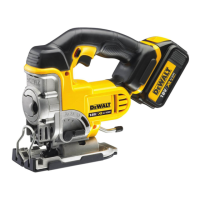
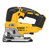
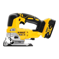
Tilsigtet Brug
Dine DCS334 og DCS335 stiksave er designet til professionel
skæring af træ, stål, aluminium, plastik og keramiske materialer
på forskellige arbejdspladssteder (fxbyggepladser).
MÅ IKKE anvendes under våde forhold eller i nærheden af
brændbare væsker ellergasser.
Disse kraftige stiksave er professionelt elektriskværktøj.
LAD IKKE børn komme i kontakt med værktøjet. Overvågning
er påkrævet, når uerfarne brugere anvender detteværktøj.
• Dette produkt er ikke beregnet til anvendelse af personer
(inklusive børn) med nedsatte fysiske, sensoriske eller
mentale handicaps; mangel på erfaringer, viden eller
færdigheder, medmindre de er under overvågning af en
person, der er ansvarlig for deres sikkerhed. Børn må aldrig
efterlades alene med detteprodukt.
Datokodeposition (Fig. A)
Datokoden
10
, der også inkluderer produktionsåret, er tryk
påhuset.
Eksempel:
2020 XX XX
Produktionsår
 Loading...