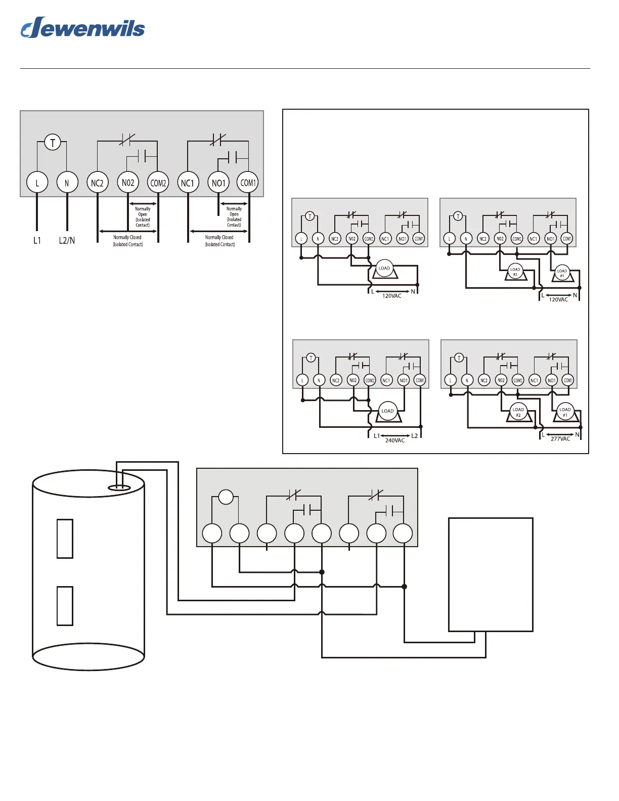
DIGITAL BOX TIMER TERMINAL DESIGNATIONS
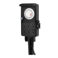
120VAC Application Controlling
One 120VAC Load
120VAC Application Controlling
Two 120VAC Loads
240VAC Application Controlling
One 240VAC Load
*J1 & J2 are 16 AWG jumper wire for the timer power supply.
277VAC Application Controlling
Two 277VAC Loads
DIGITAL BOX TIMER TYPICAL APPLICATIONWIRING DIAGRAMS
Note: Digital Box timer is capable of being congured for 120VAC, 240VAC.
L = Line | N = Neutral | NO = Normally Open | NC = Normally Closed
COM = Common Terminal | J = Jumper Wire | T = Timer
or 277VAC.
(J1)
(J1)
(J2)
(J2)
(J1)
(J1)
(J2)
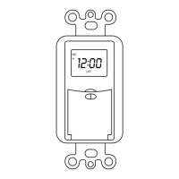
Dewenwils Outdoor Digital Box Timer INS TALLATION INSTRUCTIONS
Made in China
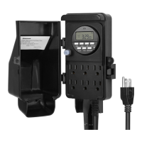
HOT WATER HE ATER TYPICAL WIRING DIAGRAM
N NC2 N02 COM2 NC1 NO1 COM1
T
L
L2/N
HOT W ATER TANK
Circuit Breaker Box
240 VAC
(Dualphase)
L1
J1
J2
120 VAC
120 VAC
120 VAC
120 VAC
120 VAC
120 VAC
L1 L2
* J1 & J2 are 16 AWG jumper wire for the timer
power suppl y.
One-year Limited Warranty
Dewenwils warrants this product to be free from defects in material and workmanship for a period o f one year from the date of purchase.
Warranty will be void if damage is
caused by misuse or improper installation. Please contact us if you have any questions.
Email: support@dewenwils.com.
Our dedicated customer service team will get back to you within 24 hours.
Digital Box Timer
Digital Box Timer
Digital Box Timer
Digital Box Timer
Digital Box Timer
Digital Box Timer