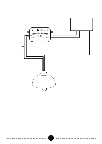
Wiring Diagram
02
1. Turn off the power to the main circuit breaker or fuse box working area
before installation.
2. At the input "L" Red line is the hot wire, "N" Blue line is the neutral wire.
At the output "L" Black line is the hot wire, "N" White line is the neutral
wire. Do not connect the "L" (hot wire) and "N" (neutral wire)mistakenly.
3. Connect the power to the "input" side, and the load to the "output" side
carefully.
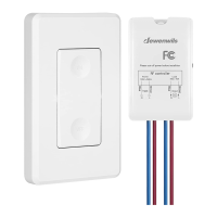
4. The wireless switch kit only needs to connect with the hot wire and
neutral wire. The "G" Green line (ground wire) just needs to be connected
as normal.
5. After connecting, use the wiring cap to cover it.
Power Input
G (Green)
L (Black)
L (Red)
N (White)
N (Blue)