DSI-5A-D9M
TECHNICAL REFERENCE MANUAL
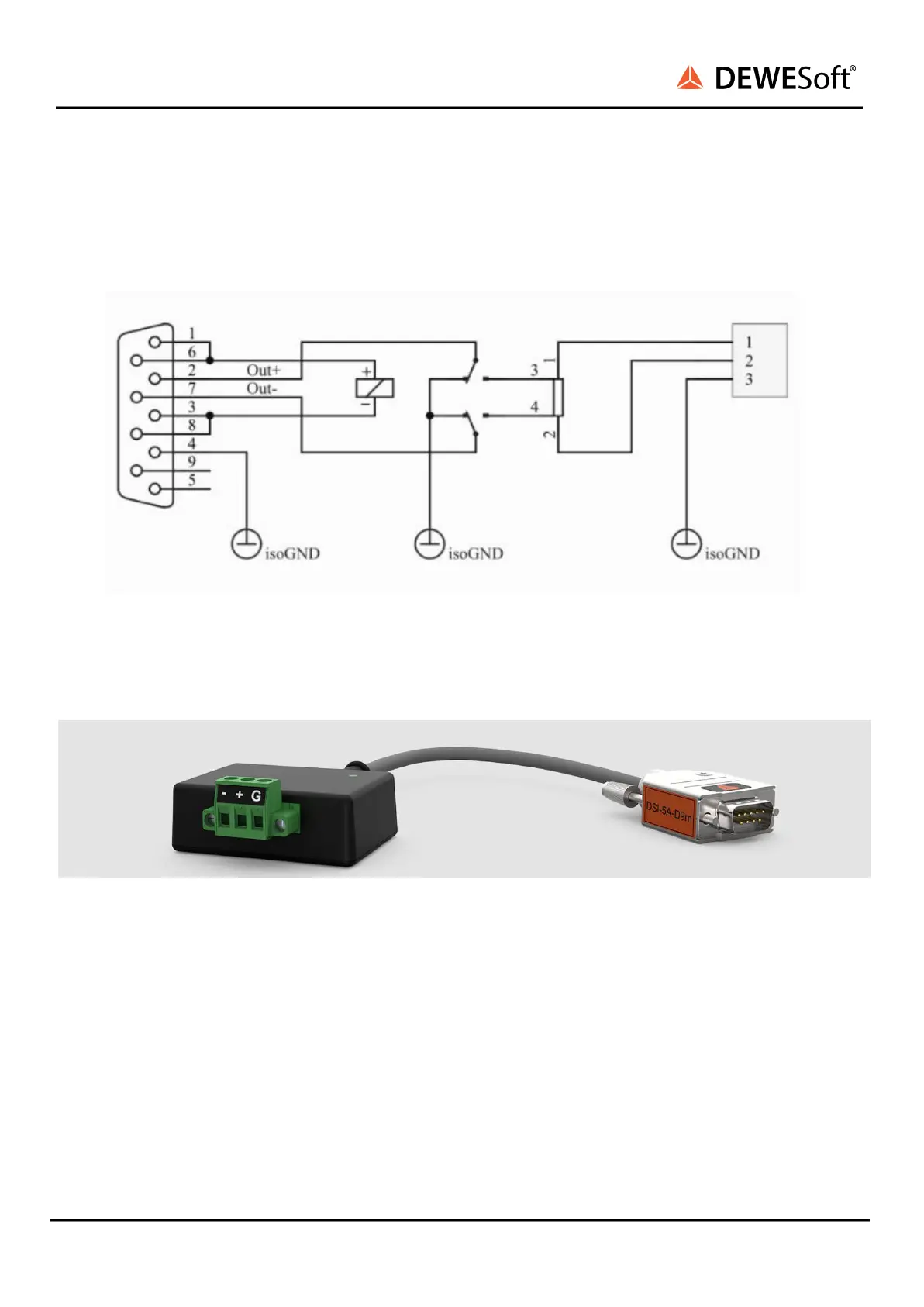
Signal Outputs are disconnected from DSUB connector contacts until adapter and its DSUB connector
is connected to DAQ to protect the user from possible high voltage present on the contacts when
current source input is already connected to the input 3pin plug. Protective switch is powered by DAQ
Exc. Voltage.
Illustration 5: DSI-5A-D9M Adapter partial schematic
6. Operation
Illustration 4: DSI-5A-D9M Adapter
Signal output enable indicator LED is turned ON (green) when output signal is present on the Signal
Output pin 2 and 7.
6.1. DSI adapters / TEDS sensor support
Since there is an built-in TEDS device in the adapter itself and if DSI adapters/TEDS sensors under
Settings are selected, adapters will be recognised and parameters will be set automatically. Please
check if Dewesoft enables scanning for DSI adapters.
DSI-5A-D9M V20-1 7/17