14
EN
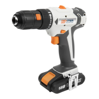
Light ON/OFF ash Status
Red on
________
Charging
Red ash
_ _ _ _
Defective Battery
Green on
________
Fully Charged
Green ash
_ _ _ _
Hot/Cold Delay
OPERATING INSTRUCTIONS
1. HOW TO USE THE BELT CLIP (SEE FIG.B1, B2)
Screw the Belt clip (6) on the tool with the screw provided in the plastic bag. The Belt clip can be
hooked on your belt or pocket, etc.
2. ON / OFF SWITCH (SEE FIG. C)
Depress the On/Off switch to start and release it to stop your drill. The on/off switch is tted with a
brake function which stops your chuck immediately when you quickly release the switch.
It is also a variable speed switch that delivers higher speed and torque with increased trigger
pressure. Speed is controlled by the amount of switch trigger depression.
WARNING: Do not operate for long periods at low speed because excess heat will be
produced internally.
3. SWITCH LOCK
The switch trigger can be locked in the OFF position. This helps to reduce the possibility of accidental
starting when not in use. To lock the switch trigger, place the rotation control in the center position.
4. REVERSIBLE (SEE FIG. D1, D2)
For drilling and screw driving use forward rotation marked “ ” (lever is moved to the left). Only
use reverse rotation marked “ ” (lever is moved to the right) to remove screws or release a
jammed drill bit.
WARNING: Never change the direction of rotation when the chuck is rotating, wait until it has
stopped!
5. TWO-SPEED GEAR CONTROL (SEE FIG. E)
The drill has a two-speed gear control designed for drilling or driving at LO (mark is 1) or HI (mark
is 2) speeds. A slide switch is located on top of the drill to select either LO or HI speed. When using
the drill in the LO speed range, the speed will decrease and the drill will have greater power and
torque. When using the drill in the HI speed range, the speed will increase and the drill will have less
power and torque.
Gear I
Low speed range: for screwdriving or working with large drilling diameter
Gear II
High speed range: for working with small drilling diameter
WARNING: To prevent gear damage, always allow the chuck to come to a complete
stop before changing the direction of rotation or the two-speed gear control.
6. CHUCK ADJUSTMENT (SEE FIG. F1, F2)
To open the chuck jaws rotate the front section of the chuck in direction 1. Insert the drill bit between
the chuck jaws and rotate the front section in the direction 2. Ensure the drill bit is in the center of
the chuck jaws. Finally, rmly rotate the front chuck section in the directions 2. Your drill bit is now
clamped in the chuck.
 Loading...