Page 10 ;&(%$*4.8"4,7%<'*#$"&8#=%/7*,#*%4,77%>?@@@?@AA?BCDC1 Item 57087
EF;6GH IJ6KFGLIM NFLMG6MFMO6E6GPJ
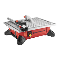
4. Slide Locking Lever under Rip Fence until the end
of the Locking Lever lines up with the end of the
Fence. Rotate Lever Knob clockwise to lock in place.
;*84*
T&4`"83%
T*W*(
T*W*(%
^8&+
5. Place Rip Fence onto Tile Saw table so
that bracket on the Locking Lever fits
perfectly over the Rip Fence Scale.
E4,7*
T*W*(%
S(,4`*$
6. Use Scale to set Rip Fence to desired width of cut.
Push Locking Lever down to secure fence to table.
L8#$,77"83%$.*%N"$*(%R,'3*
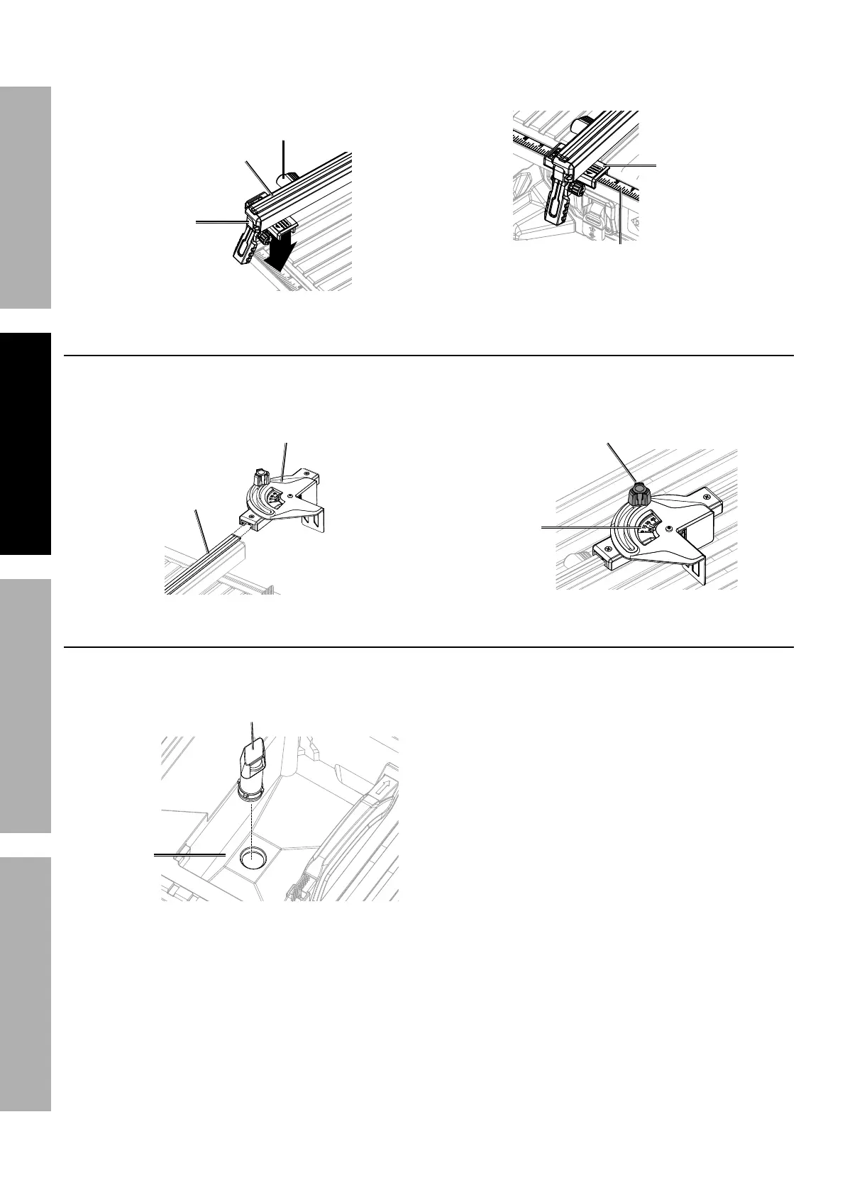
1. Place Miter Gauge on top of Rip Fence so that
grooves on each part align. Slide Miter Gauge onto
Rip Fence to desired position along the fence.
N"$*(%R,'3*
K"/%;*84*
2. Use the Angle Scale to find desired angle for the
cut and secure in place with the Gauge Lock Knob.
R,'3*%
T&4`%^8&+
F837*%
E4,7*
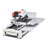
L8#$,77"83%$.*%IW*(27&)%U(,"8
1. Remove Bevel Table. Firmly push the Overflow
Drain into the hole in the bottom of water reservoir.
IW*(27&)%U(,"8
K*#*(W&"(
2. Replace Bevel Table, making sure
it fits properly in place.