Page 8 ;&(%$*4.8"4,7%<'*#$"&8#=%/7*,#*%4,77%>?@@@?@AA?BCDC1 Item 57087
EF;6GH IJ6KFGLIM NFLMG6MFMO6E6GPJ
FEE6NSTH
GI%JK6!6MG%E6KLIPE%LMcPKH%;KIN%FOOLU6MGFT%IJ6KFGLIM-%
G'(8%$.*%J&)*(%E)"$4.%&2%$.*%$&&7%&22=%(*5&W*%$.*%E,2*$V%^*V=%,89%'8/7'3%$.*%$&&7%
2(&5%"$#%*7*4$("4,7%&'$7*$%+*2&(*%/*(2&(5"83%,8V%/(&4*9'(*%"8%$."#%#*4$"&81
M&$*- For additional information regarding the parts listed in the following pages,
refer to the Assembly Diagram near the end of this manual.
N&'8$"83%$.*%E,)
N&'8$"83%E,89*(
1. Select a workbench or mounting location that is
able to support the weight of the Tile Saw, plus
any additional weight placed on it during use.
2. Make sure there are no hidden electric wires,
cables or other obstructions that may interfere
with the mounting procedure or cause a hazard.
3. Mark the mounting hole locations and
drill the appropriate size holes for the
mounting bolts (not included).
4. Mount the Tile Saw using Bolts,
washers and nuts (not included).
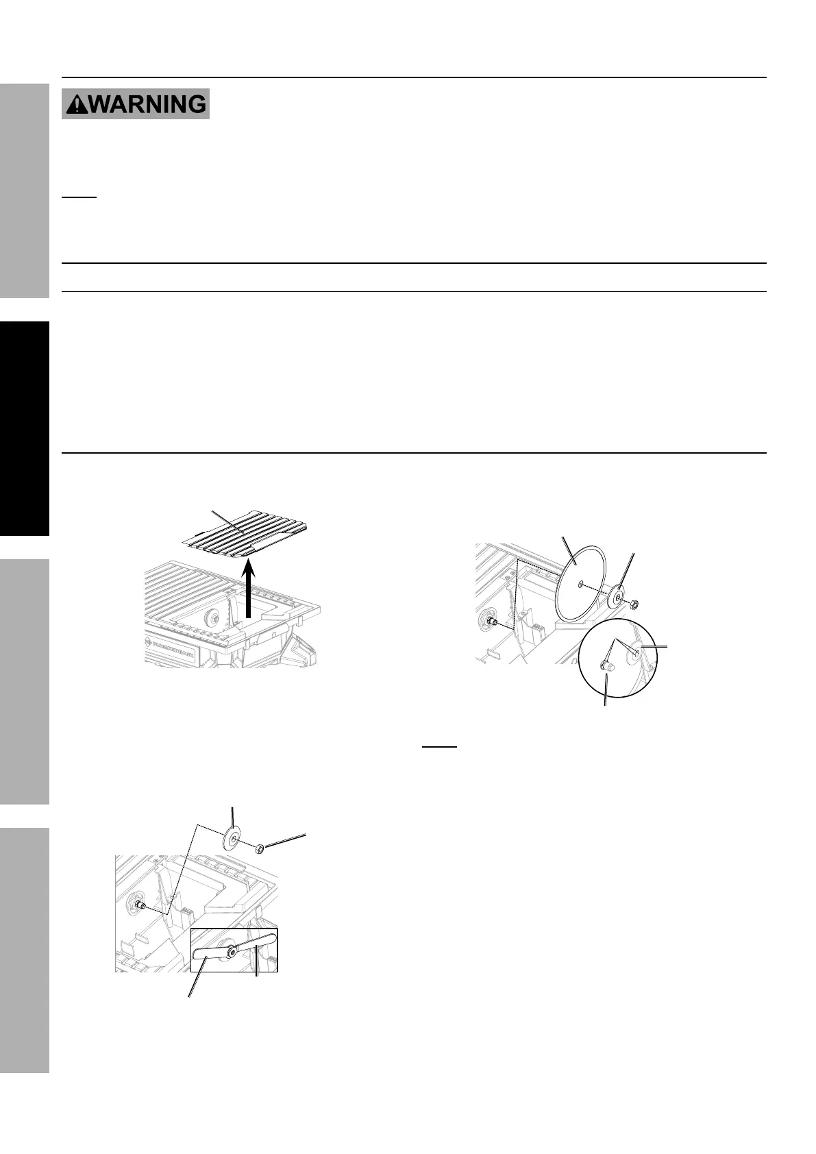
L8#$,77"83%S7,9*
1. Unplug the Saw and remove Bevel Table.
S*W*7%G,+7*
2. Place Hex Wrench onto Spindle Nut, then place
Slotted Wrench onto Spindle. Hold Slotted
Wrench firmly to prevent the Spindle from moving
and loosen Spindle Nut in a counterclockwise
direction. Remove Spindle Nut and Outer
Flange, leaving Inner Flange on the Spindle.
E7&$$*9%
Q(*84.
]*a%
Q(*84.
E/"897*%
M'$
I'$*(%;7,83*
3. Place Saw Blade onto Spindle with
arrows pointing in a counterclockwise
direction. Replace Outer Flange.
Flats
E,)%S7,9*
;7,83*
E/"897*
I'$*(%
;7,83*
M&$*- The flats on flanges should
align with flats on Spindle.
4. Replace Spindle Nut. Make sure flat side
of Spindle Nut touches Outer Flange.
5. Tighten Spindle Nut securely using wrenches.