Quick Start Guide
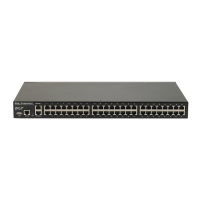
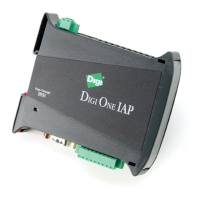
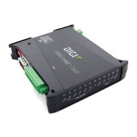
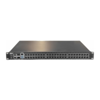
PortServer® TS Family
Welcome to your Digi product
Get started: This guide helps you with initial product setup. Need more? Find additional supporting material for
this product at www.digi.com/support/portserverts. Or connect to the online documentation by scanning
this code:
Digi Technical Support: Digi offers multiple support plans to help you get the most out of your product. For
information on Technical Support plans and pricing, contact us at 877.912.3444 or visit www.digi.com/support.
Documentation feedback: To provide feedback on this documentation, send your comments to
techcomm@digi.com.
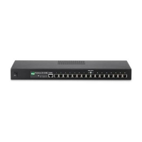
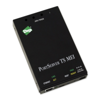
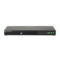
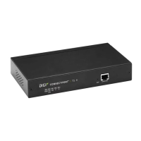
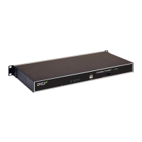
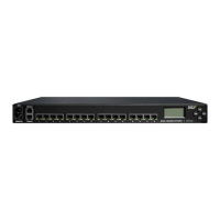
1 Verify your components
Included equipment Required equipment
Note A loose label sticker that includes the unique device password is included in the box. Retain this label sticker with your hardware records.
This default password will be needed if the device is factory reset and you want to access the web UIon the device.
2 Confirm serial pinouts
Step 1: Configure DIP switches (MEI models only)
For PortServer TS 1-4 port models, if the connected device is not EIA-232, set the DIP switches as shown for the serial port according to your serial device requirements.
PortServerTS 1-4 port DIP Switch settings: PortServer TS P MEI DIP switch settings:
Switch settings
Up/On
Down/Off
For PortServer TSPMEI series only, in EIA-232 mode, if switch 3 is
down, 9V power is provided on pin 9 (DTR). If switch 3 is up, power on
pin 9 is disabled and 5V power can be enabled on pin 1 (RI) through
the software interface. If using EIA-422 or EIA-485, the DIPswitch
settings are the same as for any other PortServer TS 1-4 MEI model.
If switch 4 is up, the termination resistor is connected. If switch 4 is down, the termination resistor is not connected.
Step 2: Review serial pinouts
Pin positions for connecting serial devices
Note For additional information on Digi part numbers
for serial cables and adapters, refer to the Cable Adapter Insert Card.
Pin # on 10-wire
connector
Pin # on 8 wire
connector
EIA-232 MEI versions only
EIA-422/485 Full-
Duplex
EIA-485
Half-Duplex
1 RI TxD- N/A
2 1 DSR* RxD- DATA-
3 2 RTS RTS+ N/A
4 3 CGND CGND CGND
5 4 TxD TxD+ N/A
6 5 RxD RxD+ DATA+
7 6 SGND SGND SGND
8 7 CTS CTS+ N/A
9 8 DTR RTS- N/A
10 DCD* CTS- N/A
*Use the Altpin setting to swap these two signals.
Note The CTS and RTS control signals are available as separate differential signals in the EIA-
422/EIA-485 4-wire mode. Do not use these differential signals in 2-wire mode. The CTS and
RTS differential signals are not terminated or biased internally. Any termination or biasing
must be done externally.
Serial port pin assignments
© 2019 Digi International Inc.
Digi, Digi International, and the Digi logo are trademarks or registered trademarks in the United States and other countries worldwide. All other trademarks mentioned in this document are the
property of their respective owners.