9XTend-PKG-U™ USB RF Modem User’s Guide
43
4.1. Addressing
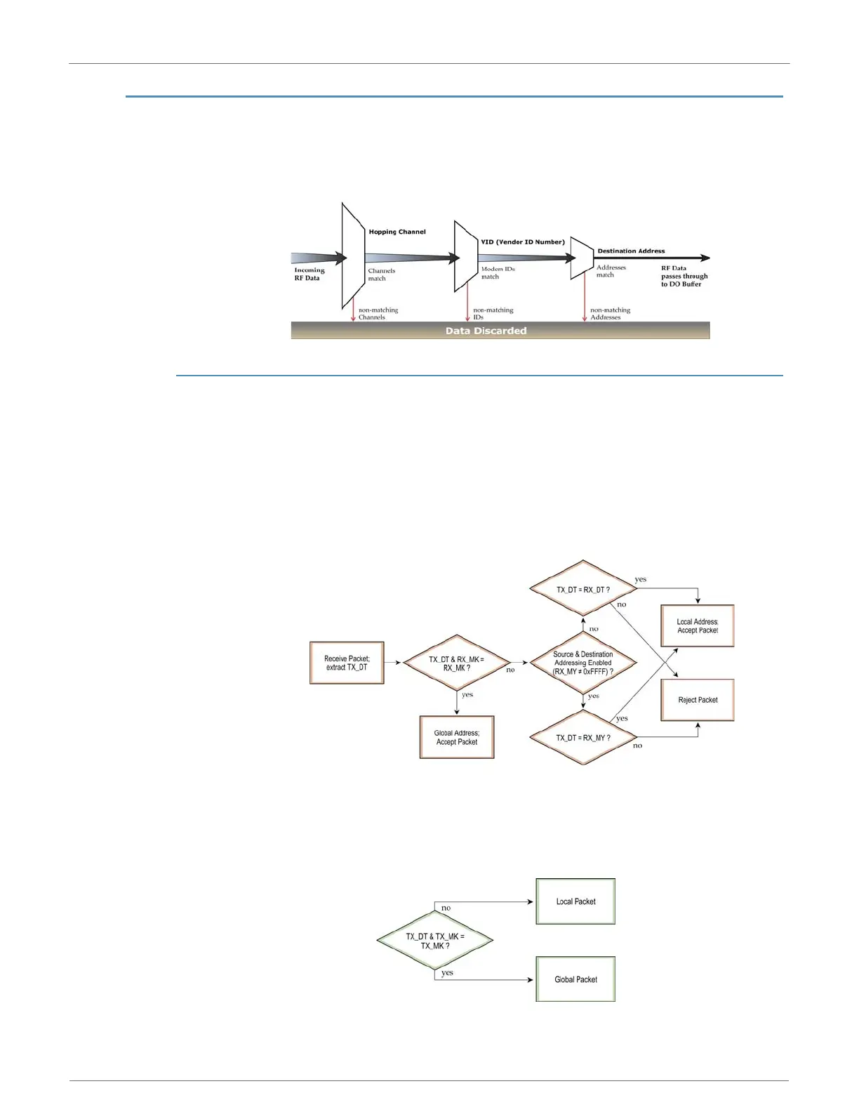
Each RF packet contains addressing information that is used to filter incoming RF data. Receiving
modules inspect the Hopping Channel (HP parameter), Vendor Identification Number (ID parame-
ter) and Destination Address (DT parameter) contained in each RF packet. Data that does not pass
through all three network security layers is discarded.
Figure 4-01. Addressing layers contained in the RF packet header
4.1.1. Address Recognition
Transmissions can be addressed to a specific modem or group of modems using the DT (Destina-
tion Address) and MK (Address Mask) commands. A receiving modem will only accept a packet if it
determines the packet is addressed to it, either as a global or local packet. The receiving modem
makes this determination by inspecting the destination address of the packet and comparing it to
its own address and address mask [refer to the figure below].
Figure 4-02. Address Recognition (@ the Receiving RF Modem)
TX_DT = Destination Address of transmitting modem
RX_DT = Destination Address of receiving modem
RX_MK = Address Mask of receiving modem
RX_MY = Source Address of receiving modem
The transmitting modem determines whether the packet is intended for a specific node (local
address) or multiple nodes (global address) by comparing the packet's destination address (DT)
and its own address mask (MK) [refer to the figure below]. It is assumed that the address masks
on the transmitting modem and receiving modem have been programmed to the same value for
proper operation in each RF Communication Mode.
Figure 4-03. Address Recognition (@ the Transmitting RF Modem)

 Loading...

