TN198 Page 8 of 11
TN198.doc\
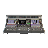
Routing of internal cables (dual Optic option shown)
Note above pictures show spiral wrap, this is only fitted AFTER the connections have been
completed to the Optocore PCB.
Ensure all cables are routed to avoid sharp edges. The correct route takes the cables around
chassis parts with protective plastic edging. If this does not appear to be present, please contact the
factory.
The cables are routed down to the top of the engine PCB.
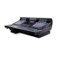
As you look at the back of the Optocore Card, the 8 optical sockets are laid out from left to right. The
optical cables attached to each HMA connector are labelled A and B on the cables themselves.
Connect the optical cables according to the table above as per the picture below.
The picture shows the 2 loop option connected. Only 2 pairs are fitted for a single loop version.
Note the A leg cables have black sleeves.
Re-check the optical cables are connected in the correct order. This is very important!
Slide the engine tray in whilst ensuring optic fibres are arranged to avoid the fan when it is re
installed.