ZYBO™ FPGA Board Reference Manual
Copyright Digilent, Inc. All rights reserved.
Other product and company names mentioned may be trademarks of their respective owners.
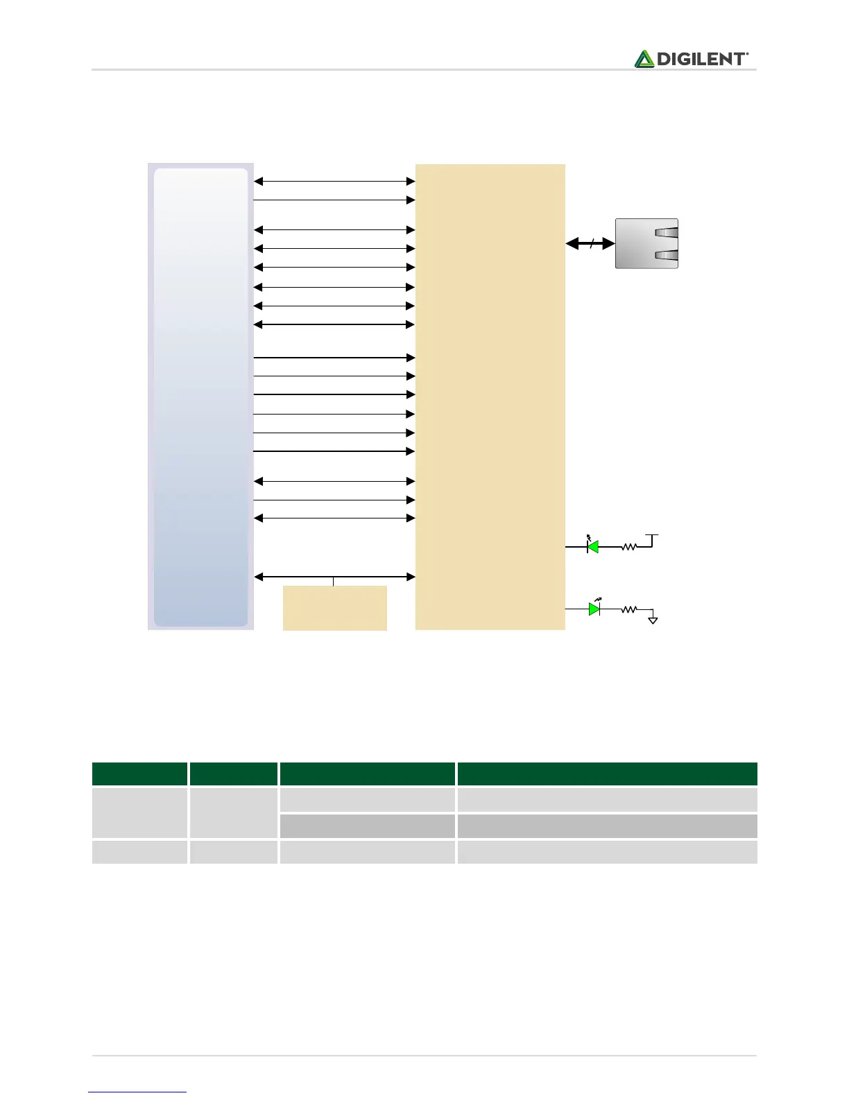
After power-up the PHY starts with Auto Negotiation enabled, advertising 10/100/1000 link speeds and full duplex.
If there is an Ethernet-capable partner connected, the PHY automatically establishes a link with it, even with the
Zynq not configured.
MIO24
MIO52
MIO53
Zynq-7
MDIO
8
MDC
MIO23 RXD0/SELRGV
Realtek RTL8211E
RJ-45 with
magnetics
RXD1/TXDLY
RXD2/AN0MIO25
MIO27
MIO26 RXD3/AN1
RXCTL/PHY_AD2
RXCMIO22
MIO18
MIO17 TXD0
TXD1
TXD2MIO19
MIO21
MIO20 TXD3
TXCTL
TXCMIO16
E17
F16 INTB
PHYRSTB
CLK125L16
DSC1121CE5
50 MHz
Oscillator
CKXTAL1PS_CLK
ACT LED (LD7)
LINK LED (LD6)
LED0/PHY_AD0
LED1/PHY_AD1
Figure 7. Ethernet PHY signals.
Two status indicator LEDs are on-board near the RJ-45 connector that indicate traffic (LD7) and valid link state
(LD6). Table 5 shows the default behavior.
Link, Energy Efficient Ethernet (EEE) mode
Transmitting or Receiving
Table 5. Ethernet status LEDs.
The Zynq incorporates two independent Gigabit Ethernet Controllers. They implement a 10/100/1000 half/full
duplex Ethernet MAC. Of these two, GEM 0 can be mapped to the MIO pins where the PHY interfaces. Since the
MIO bank is powered from 1.8V, the RGMII interface uses 1.8V HSTL Class 1 drivers. For this I/O standard an
external reference of 0.9V is provided in bank 501 (PS_MIO_VREF). Mapping out the correct pins and configuring
the interface is handled by the ZYBO board definition file.