Do you have a question about the Digilent Arty Z7 and is the answer not in the manual?
Details the dual-core ARM Cortex-A9 processor and its integration with FPGA logic.
Describes DDR3 memory and Quad-SPI Flash on the Arty Z7 board.
Explains power sources for the Arty Z7, including USB and external supplies.
Covers the Gigabit Ethernet PHY and USB-JTAG, USB-UART, USB OTG interfaces.
Details HDMI ports for audio/video and PWM audio output.
Lists the available switches, buttons, and LEDs for user interaction.
Describes Pmod ports and the Arduino/chipKIT shield connector.
Compares the Arty Z7-10 and Arty Z7-20 based on Zynq part and I/O capabilities.
Explains compatibility with Vivado, Petalinux, and SDSoC for design.
Details using external power supplies and batteries for the Arty Z7.
Describes the on-board power management unit and voltage supply circuits.
Outlines the Zynq APSoC's two main subsystems: Processing System and Programmable Logic.
Details external components connected to the Multiplexed I/O (MIO) pins.
Explains the three stages of the Zynq boot process: BootROM, FSBL, and user application.
Describes microSD, Quad SPI Flash, and JTAG boot modes for the Arty Z7.
Lists attributes of the Spansion S25FL128S Quad SPI flash memory.
Details the IS43TR16256A-125KBL DDR3 memory component and its interface.
Explains the FTDI FT2232HQ chip for USB-UART and USB-JTAG communication.
Details the microSD slot wiring, pinout, and its use for storage and booting.
Describes the Microchip USB3320 USB 2.0 Transceiver Chip used for the USB Host port.
Covers the Realtek RTL8211E-VL PHY for 10/100/1000 Ethernet connection.
Explains the function of the LINK (LD8) and ACT (LD9) LEDs for Ethernet status.
Describes the two HDMI ports (source and sink) and TMDS signaling.
Details auxiliary signals like CEC, DDC, HPD, and 5V supply for HDMI.
Explains the 50 MHz PS clock and 125 MHz PL clock inputs.
Covers LEDs, switches, and push buttons for user interaction with the board.
Details the two tri-color LEDs and how to control their colors.
Explains the audio output circuit using a Sallen-Key Butterworth low-pass filter.
Describes how PWM signals are used to generate analog audio output.
Explains power-on reset and the function of the PROG push button.
Details the SRST button for resetting the processor subsystem without disturbing debug.
Describes the high-speed Pmod ports and their signal routing.
Covers compatibility with Arduino/chipKIT shields and the pinout.
Details voltage characteristics and series resistors for shield digital I/O pins.
Explains how analog inputs are connected and scaled for the XADC module.
| Brand | Digilent |
|---|---|
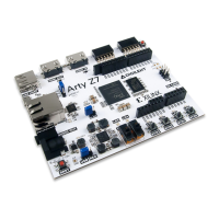
| Model | Arty Z7 |
| Category | Motherboard |
| Language | English |