EasyManua.ls Logo

Digilent ZYBO - Page 3

Digilent ZYBO
27 pages
Print Icon
To Next Page IconTo Next Page
To Previous Page IconTo Previous Page
Loading...
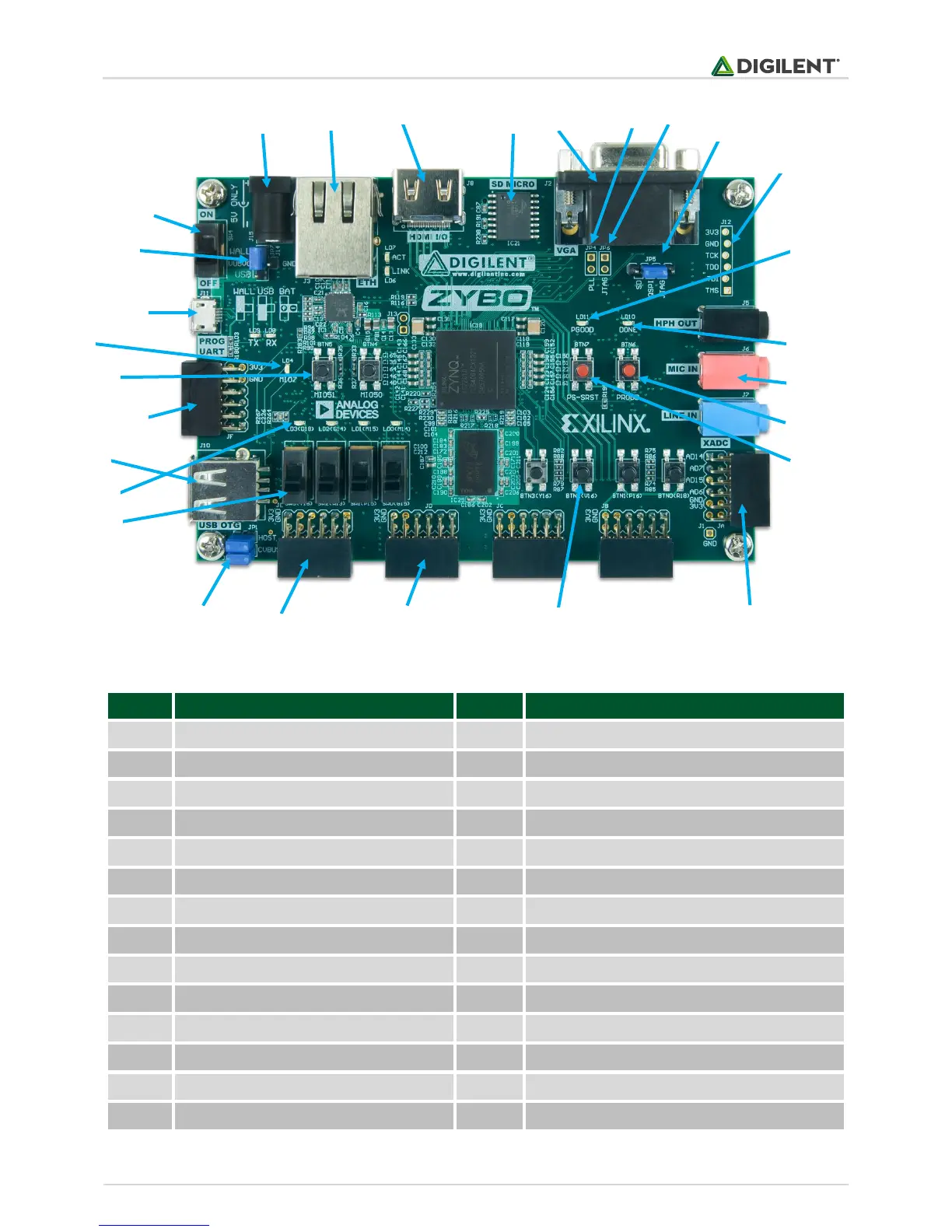
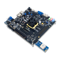
ZYBO™ FPGA Board Reference Manual
Copyright Digilent, Inc. All rights reserved.
Page 3 of 26
Callout
Component Description
Callout
Component Description
1
Power Switch
15
Processor Reset Pushbutton
2
Power Select Jumper and battery header
16
Logic configuration reset Pushbutton
3
Shared UART/JTAG USB port
17
Audio Codec Connectors
4
MIO LED
18
Logic Configuration Done LED
5
MIO Pushbuttons (2)
19
Board Power Good LED
6
MIO Pmod
20
JTAG Port for optional external cable
7
USB OTG Connectors
21
Programming Mode Jumper
8
Logic LEDs (4)
22
Independent JTAG Mode Enable Jumper
9
Logic Slide switches (4)
23
PLL Bypass Jumper
10
USB OTG Host/Device Select Jumpers
24
VGA connector
11
Standard Pmod
25
microSD connector (Reverse side)
12
High-speed Pmods (3)
26
HDMI Sink/Source Connector
13
Logic Pushbuttons (4)
27
Ethernet RJ45 Connector
14
XADC Pmod
28
Power Jack
Table 1. ZYBO Device Diagram.
1
2
3
4
5
6
7
8
9
10
11
12
13
14
15
16
17
18
19
20
21
22
23
24
25
26
27
28

Related product manuals