AMBE-2000™ Vocoder Chip Users Manual
Version 4.92, June, 08
DVSI Confidential Proprietary, Subject to Change Page 18
Visit us at www.dvsinc.com
3.4 Associated Chip Delay
The associated delay due to the coding/decoding algorithm is shown below
Encoder Delay
Algorithmic Delay = 32 ms
Encoder Processing Delay = 11.5 ms
Decoder Delay
Algorithmic Delay = 10 ms
Decoder Processing Delay = 7.5 ms
Total Delay
= 32 ms + 11.5 ms + 1 ms* +10 ms +7.5 ms = 62 ms
Frame Processing Delay =
11.5 ms (encoder) + 1 ms* + 7.5 ms = 20 ms
* 1ms of idle time between encode and decode sequence.
3.5 Crystal / Oscillator Usage
The AMBE-2000™ Vocoder Chip has an input clock frequency of 16.384 MHz. Two options are outlined below in providing
this signal. The CLOCK_MODE pin 51 must be set appropriately for the option used.
The following points should be noted when designing any printed circuit board layout:
• Keep the crystal and external capacitors as close to the CLK_I and CLK_I2 pins as
possible to minimize board stray capacitance.
• Keep X2/CLKIN and X1 away from high frequency digital traces (example CLKOUT)
to avoid coupling.
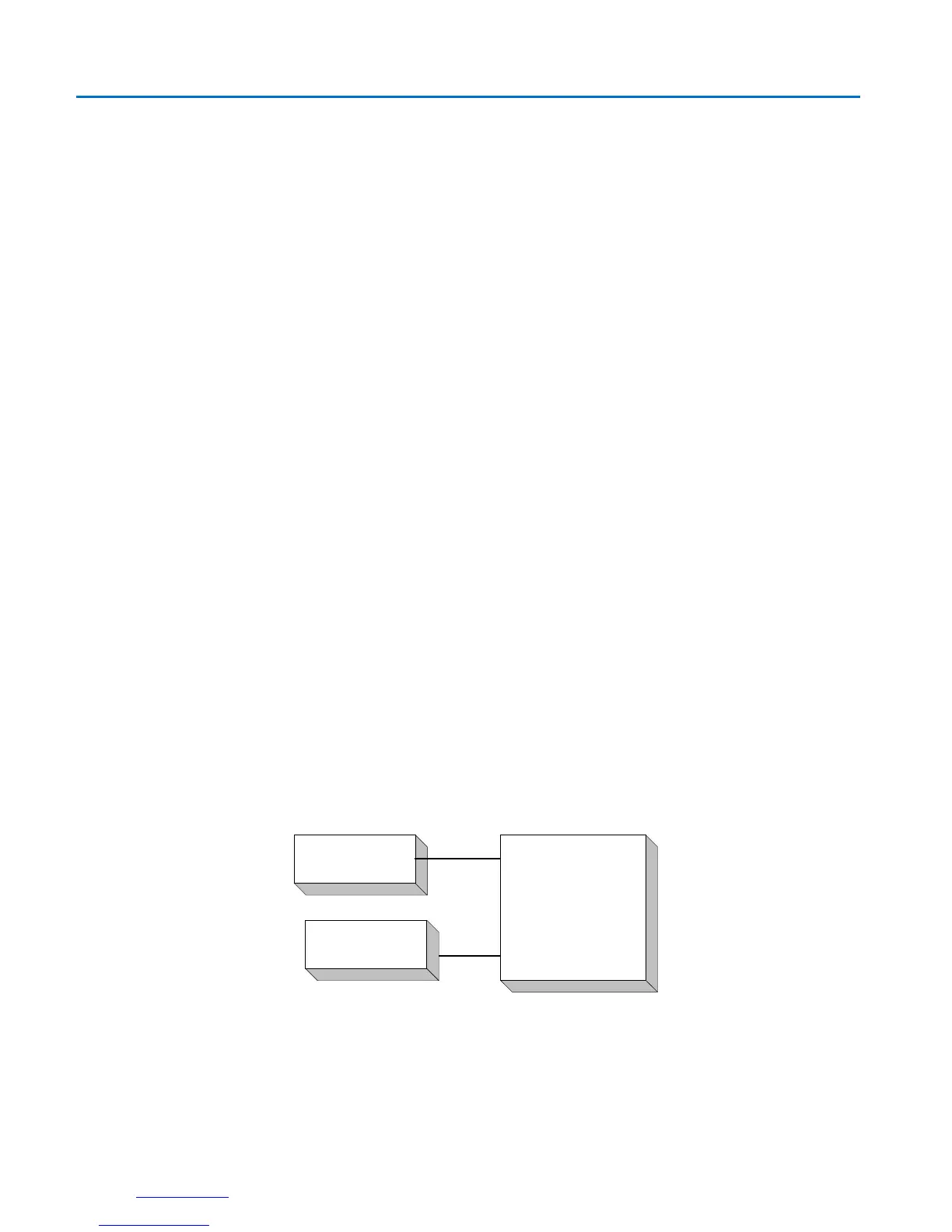
3.5.1 TTL Clock Source
If CLOCK_MODE pin is low then a TTL/CMOS source is used as the clock input. Connect X2/CLKIN and X1 as follows:
Figure 3-C X2/CLKIN and X1 with TTL Clock Source
AMBE-2000
X2/CLKIN (pin 68)
X1 (pin 67)
16.384 MHz
TTL/CMOS Clock
Source
Unconnected
3.5.2 Crystal Oscillator
The Crystal Oscillator option is selected with CLOCK_MODE pin set to a high level. To use the crystal oscillator, connect the
crystal across X2/CLKIN and X1 along with one external capacitor from each of these pins to ground. The recommended
value for C1 and C2 is 10 pF.