4
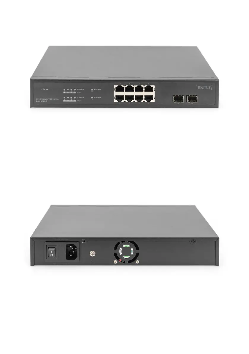
5. External Component Description
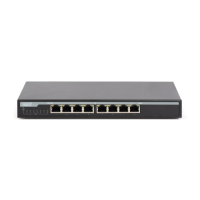
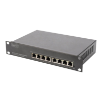
Front Panel
The front panel consists of LED indications and network ports.
PWR LED: The Power LED lights up when the Switch is connected to a power source.
Link/Act LED: The Link/Act LED flashes which indicates a network link through the
corresponding port. Blinking indicates that the Switch is either sending or receiving
data to the port.
PoE indicator: constant brightness indicates that the PD device is connected to the
corresponding port, and extinguished indicates that the port is not powered or no PD
device is found.
Real Panel
The rear panel view of the Switch consists of an AC power connector.
Power outlet: Supports input voltages 100-240VAC, 50/60Hz.
Switch: Used to connect the power supply.
Fuse: Prevent affect the power grid from equipment short circuit.
(Tank containing a spare fuse)
Grounding: use specialized ground lead connect.
 Loading...