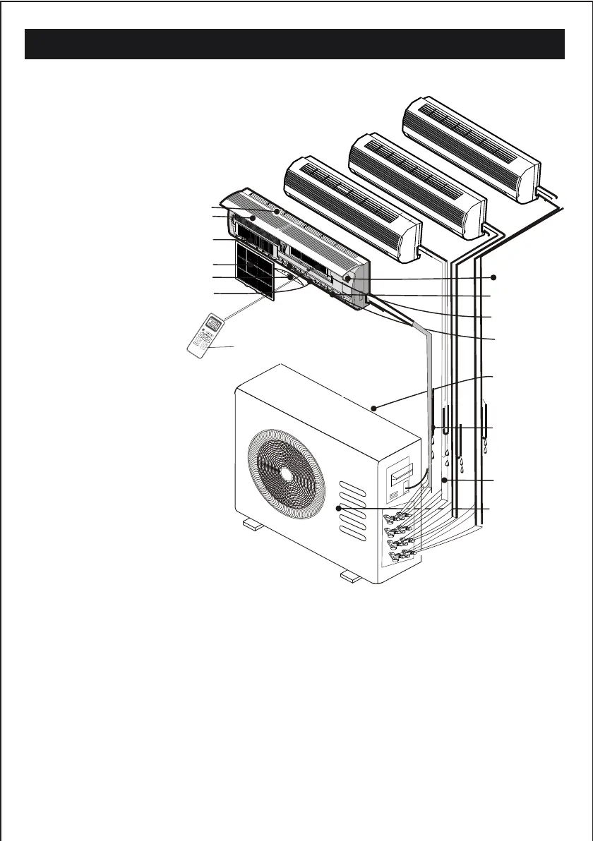
NAMES OF PARTS
Note: the above figures are only intended to be a
simple diagram of the appliance and may not
correspond to the appearance of the units that
have been purchased.
MO
D
E
F
AN S
LE
E
P
E
C
O
T
IME
R
S
W
I
N
G
IFE
E
LC
L
E
A
N
MU
T
E
H
EAL
T
H
D
IS
PL
A
Y
S
W
I
N
G
I SE
T
TUR
B
O
15
1. Air Intake
2.
3. Electrostatic Filter (optional)
4. Air Filter
5.
6. Air Outlet
7.
8. Vertical Adjustment Louver
9. Charcoal Filter (optional)
10. Horizontal Adjustment Louver
11. Air Intake
12 .Drain Hose
13 .Pipes and Power Connection Cord
14. Air Outlet
15. Remote Controller
Front Panel
Display Panel
Emergency Panel
Note: Condensate water drains
at COOLING or DRY operation.
Indoor unit 1
Indoor unit 2
Indoor unit 3
Indoor unit 4
1
2
3
4
5
6
7
8
9
10
11
12
13
14
Outdoor unit
 Loading...