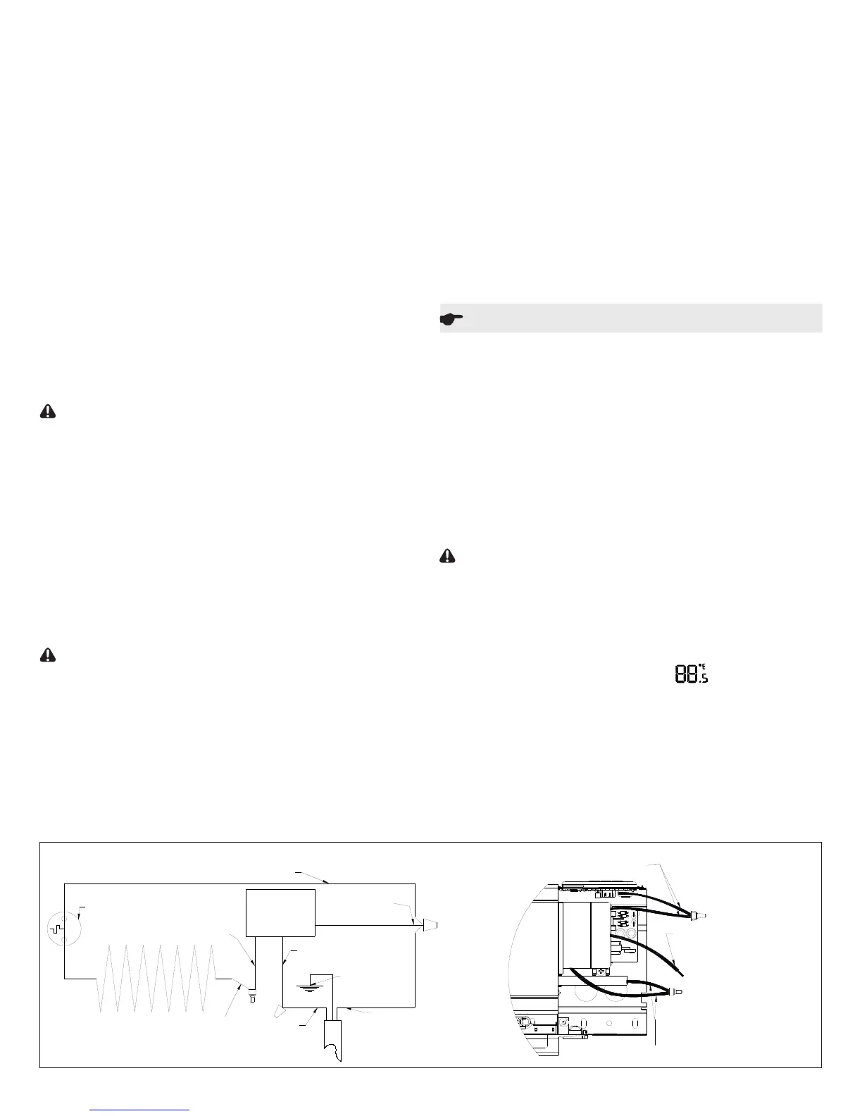
Black - Element Return Wire
Black - Element Wire
Black - Control Wire
Blue - Control Wire
Blue control wire and black element return wire are connected.
Connect L2/Neutral to these during installation.
Black wire from control.
Connect L1 to this during installation.
Yellow control wire and black element wire are connected.
Do not change during installation.
Control Board
LPC
Thermal Cutoff
Ground
L2 / Neutral
L1
Yellow - Control Wire
Operation
3. Furniture: Place furniture no closer than 3” (7.62 cm) from
the front of the Linear Proportional Convector. (Figure 1D)
4. Overhanging Solid Objects (Except Plastic): Posi-
tion Linear Convector so there is at least 14” (35.6 cm)
between the top of the heater and any solid object that
obstructs or redirects the vertical air ow out of the top of
the unit. (Figure 1C)
5. Overhanging Plastic Objects: All Plastic items that can-
not withstand extended exposure to temperatures 60º C or
higher should be kept a minimum of 20” (50.8cm) above
the unit. (Figure 1C))
!
NOTE: Ensure that when 2 Linear Proportional Convec-
tors are installed near the same corner they are both a
minimum of 6” from the corner.
Installation
All Linear Proportional Convectors must be connected from
the right side of the heater.
!
NOTE: The left hand end of the enclosure can be used as
a junction box and the space under the heater can be used
as a wireway.
CAUTION: Disconnect power supply before installation to
prevent electric shock.
1. Unpack and place Linear Proportional Convector on oor
face up, use packaging to protect oor if required. Remove
front covers.
!
NOTE: Remove the center cover, by releasing the top
rst.
!
NOTE: Heater ns can be easily bent. For optimal per-
formance ensure that they remain vertical.
2. Orient unit in desired location and mark pilot holes - top
and bottom at both ends and at least one set in middle.
3. Wire unit as per diagrams (below) and National and Local
Electrical Codes.
CAUTION: Connect heaters to a branch circuit used only
for permanently installed heater and protected by over
current devices rated or set at no more than 30 amperes.
The total connected load should not be more than 80% of
the rating of the over current devices. It may cause a re
hazard if not installed and maintained in accordance with
these instructions.
4. Position LPC, pushing cable back into wall (or conduit),
run screws through pre-selected mounting holes and
spacers (if applicable), using appropriate wall anchors, if
necessary.
1. This linear convector must be properly installed before it is
used.
2. Prior to energizing, remove all construction dirt (plaster,
sawdust, etc.) from interior and exterior of linear convector.
Dimplex linear convectors are designed and tested for safe
and trouble-free operation. All Dimplex linear convectors are
protected against overheating by a built-in thermal cutout.
Free airow throughout the linear convector is very impor-
tant for the most efcient operation of the linear convector.
Restricted airow may cause the thermal overload protector
to cycle the linear convector “ON and OFF”. A cycling linear
convector will not supply sufcient heat to the room.
CAUTION: Avoid direct contact of paper, fabric, or furni-
ture with linear convector, to prevent a possible re.
When power is rst supplied to the LPC the Setpoint Temper-
ature will ash in the temperature display area. At any time
either the + or - button can be pressed to have the tempera-
ture setpoint displayed again.
A. Setting/Temperature Display
The LPC is designed to control the temperature of a room
anywhere from 32-86°F (0-30°C). Pressing the + or - will in-
crease or decrease the desired temperature for the room to
be heated by 0.5° (in either °C or °F).
After 5 seconds the Setpoint Temperature will switch to dis-
play the intake temperature of the room.
!
NOTE: Pressing the + and - at the same time will toggle
between °C and °F.
2 www.dimplex.com
Wiring Diagram
!
NOTE: Screw should be backed off 1/2 turn from snug
position to allow free expansion and contraction of housing
and to ensure quiet operation.
5. Replace covers on unit.
!
NOTE: Install the center cover rst, by installing the top
rst, then the bottom.
Usage of Multiple Linear Proportional Convectors
Multiple Linear Proportional Convectors can be wired in par-
allel on a single circuit. To use/control multiple Linear Propor-
tional Convectors from a single source, a CONNEX
TM
control-
ler can be used. By synchronizing one CONNEX
TM
controller
to multiple LPC’s, the controller can control all of the heaters
from one location. Each component must be within 15m
(45ft) of any other component in the system for the entire
system to operate.

 Loading...