452115.66.39 · FD 9707 EN-5
Smart-RTC+ English
4.4 Electrical connection
!
Work must only be carried out by qualified personnel. Before carrying out
electrical connection work, always ensure that there is no voltage
present.
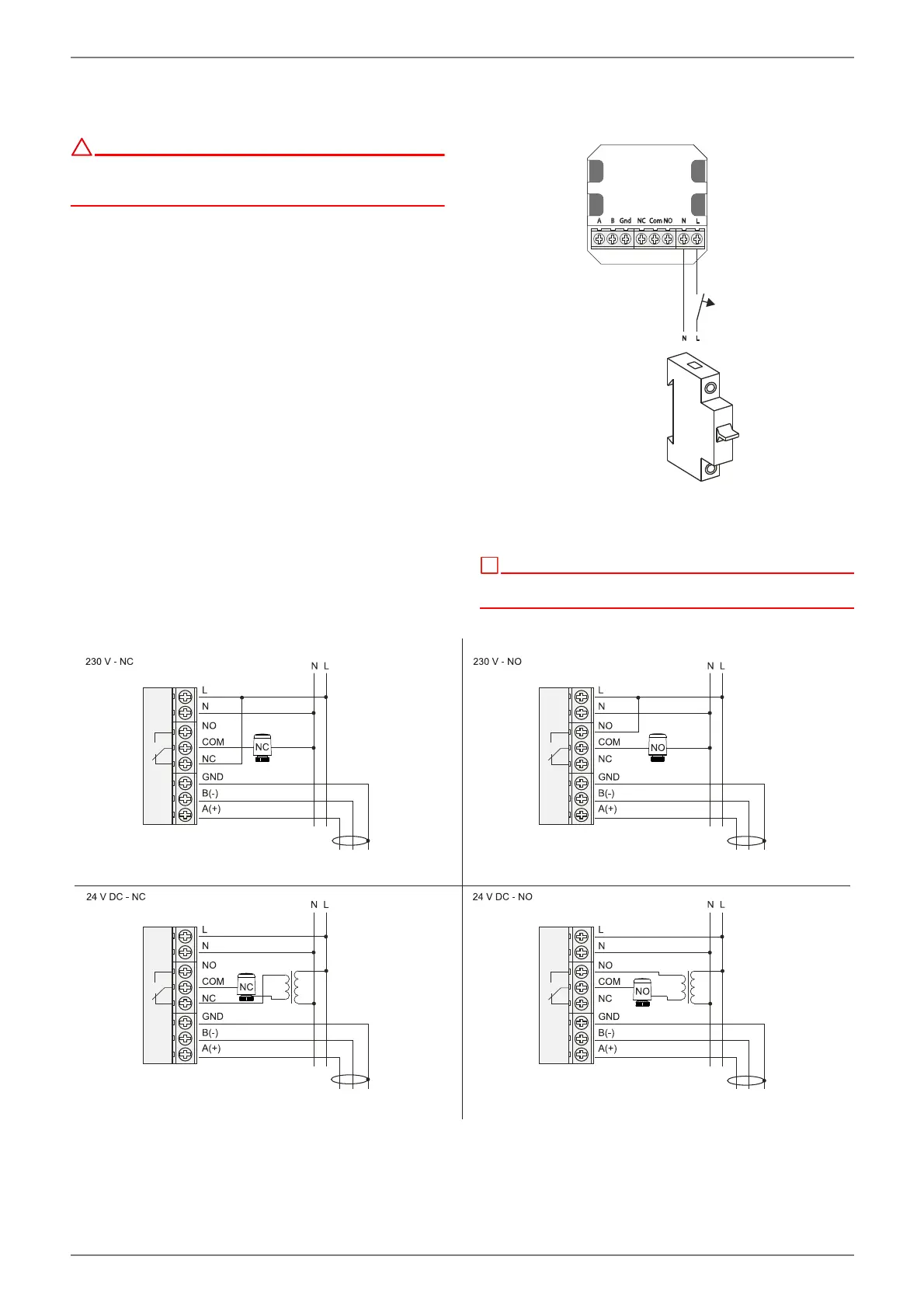
4.4.1 Power supply
The power supply is connected to terminals L and N (1~ /N,
230 V, 50 Hz) of the RTM Econ A⁄U via a 2-core cable (to be pro-
vided on-site). Cable cross sections of 0.5 mm² and 1.5 mm² are
permissible.
Fig. 4.6:
4.4.2 Control valve
The control valves must be connected in accordance with
Fig. 4.7 on page 5. The version of the control valve used (NO/
NC) and the power supply must be taken into account during this
process.
º
Because the control valves are only closed when necessary, a 230V NO-
type (normally open) control valve is recommended.
Fig. 4.7: