EN-6 452115.66.39 · FD 9707
English Smart-RTC+
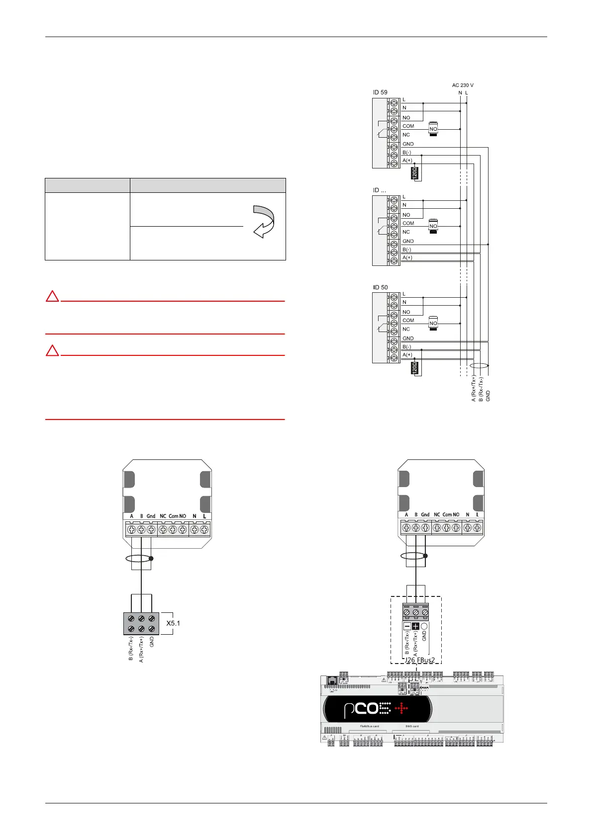
4.4.3 BUS line
A bus line must be connected on-site between the heat pump
manager (N1) and the RTM Econ A⁄U. The BUS line must have
a linear structure (Fig. 4.11 on page 7). This requires a shielded
2x 0.25 mm² cable with a maximum length of 500 m. The cable
screening is used as the GND connection.
The BUS line must be connected to the terminals in accordance
with Table 4.1 on page 6 and Fig. 4.9 on page 6 or Fig. 4.10 on
page 6 depending on the heat pump type.
Table 4.1:
!
Low voltage is present on the A / B and GND terminals of the
RTM Econ A⁄U. Line voltage (~230 V) at these terminals destroys the
electronic components of the controller.
!
A maximum of 2 heating/cooling circuits may have RTM Econ A⁄U. Up to
10 RTM Econ A⁄U are possible per heating/cooling circuit. The heat pump
manager can communicate with a maximum of 20 RTM Econ A⁄U. If the
number of rooms exceeds 20, further RTM Econ A⁄U have no
communication with the heat pump manager. A shielded 2x0.25 mm²
cable with a maximum length of 500 m must be used.
Fig. 4.8:BUS line with several room controllers
Fig. 4.9:
Fig. 4.10:
RTM Econ A⁄U Heat pump manager
A (Rx+/Tx+)
B (Rx-/Tx)-
GND
X5.1
+ / - / GND
if not
present
N1-J26
+ / - / GND