www.dimplex.eu 2007/A EN-15
Installation English
7. Installation
7.1 Remove packaging material and dispose of it cor-
rectly.
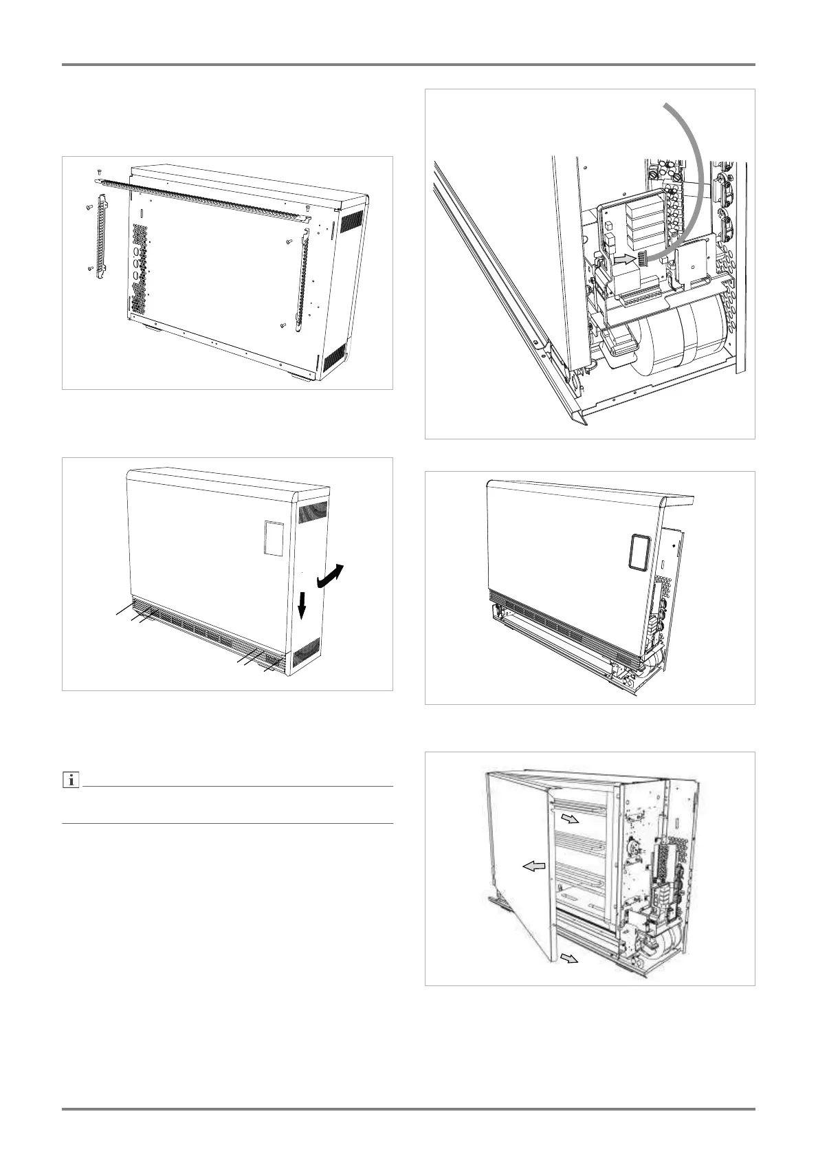
7.2 Fix the two lateral wall battens on the rear of the
device. Screw the upper wall batten to the two lateral
wall battens.
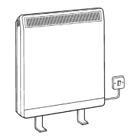
7.3 Remove the screws (A) for the side panels. Push
the side panels down (1) and swivel them out (2). After
removing the side panels, loosen the fixing screws (B)
for the front panel. Do not loosen the screws C.
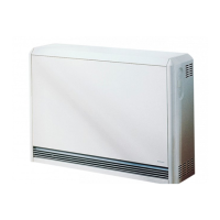
Before removing the front panel, disconnect the oper-
ating panel connection cable on the load controller.
7.4 Disconnect the connection cable.
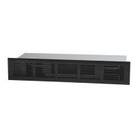
7.5 Swivel out the front panel to the front, lifting it
slightly to release it from its rear fixing.
7.6 Remove the core room cover. To do this, loosen
the three fixing screws at the side. Lift the core room
cover slightly, swivel it outwards (A) and then pull it to
the right (B).