www.dimplex.eu 2007/A EN-17
Electrical connection English
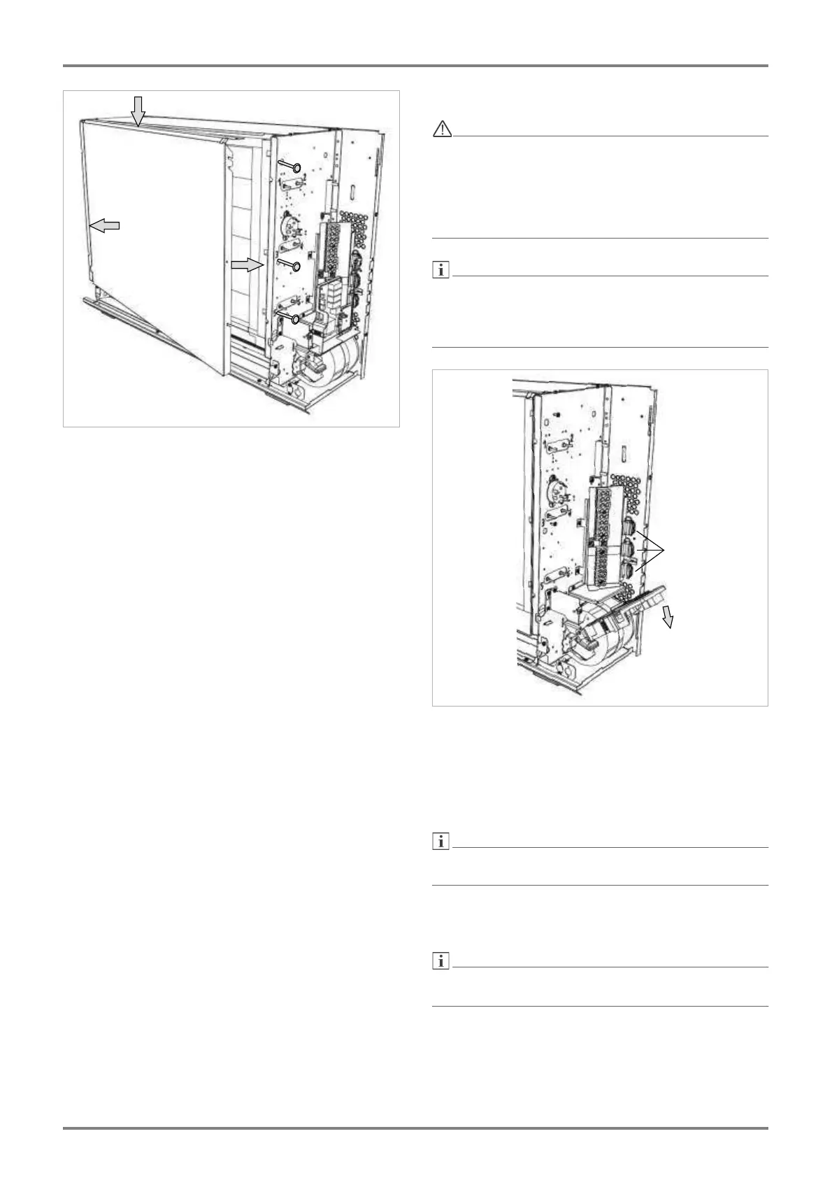
7.12 Reinsert the core room cover.
Left: The upper edge (A) of the core room cover must
rest on the partition. Slide the lateral edge (B) behind
the bevel of the partition.
Right: Insert the lateral edge of the core room cover
(C) between the thermal insulation and the partition.
Watch out for the guiding slots.
Press the core room cover firmly and fix in place with
the three screws.
8. Electrical connection
When connecting the storage heater to the
power supply, the relevant VDE, EN and IEC
standards must be observed. The technical
connection conditions of the energy supplier
or grid operator must be complied with.
There must be an all-pole disconnecting device up-
stream of the device with a distance of at least 3 mm.
This requirement is met via circuit breakers, for exam-
ple.
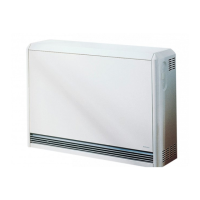
8.1 Fold the main electronics down by 90° (A) to ac-
cess the connecting terminals.
Insert the electrical connecting lines and provide
strain relief. (B). Shorten the lines so that they do not
touch any hot device surfaces during operation. Do
not route any cable loops behind or below the device!
When folding up the main electronics into the vertical
position, ensure that no lines are trapped.
Circuit diagram and connecting terminals can be
found on the next page.
T
ake care to apply appropriate torque to screws, max-
imum 1.2 Nm.