EN-18 2007/A www.dimplex.eu
English Electrical connection
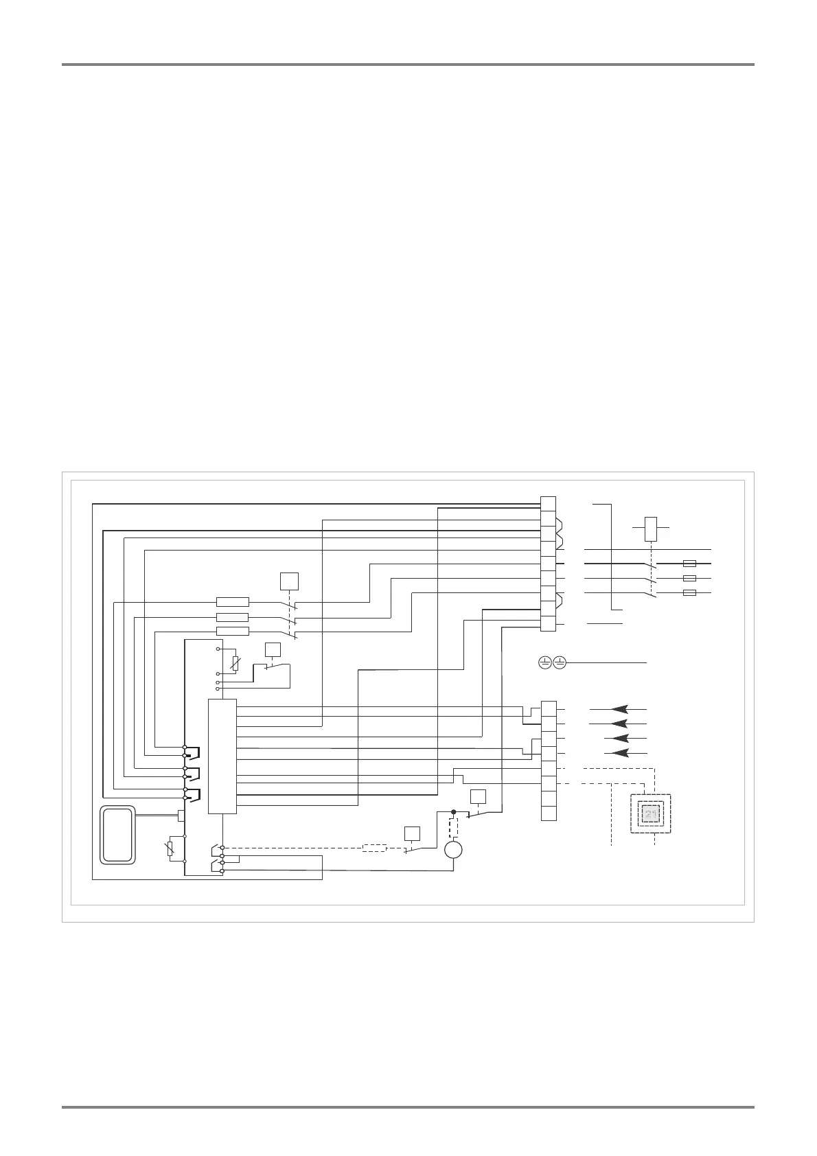
Circuit diagram
A1+, A2- DC signal charge control
A1~, A2~ AC signal charge control
Ex RT External room thermostat (optional)
K1 Heater contactor
L1, L2, L3 Phase
LE Fan control
LER Controller charge, discharge
LH Supplementary heating control
L-R Phase controller
L-SH Phase direct control
M1 Fan
N Neutral conductor
N-R Neutral conductor controller
21
230V ED%
0,91...1,43V DC
A1/Z1~
A2/Z2~
A2-
A1+
N
L-SH
2
3
4
5
6
7
N
K1
N-SH
N
L3
L2
L1
L3
L2
L1
R3
R2
R1
PE
PE
1
8
9
N-R
12
13
14
15
16
17
11
18
PTC
STR
M1
L-R
N
L
N
LH
LE
N
L
LER
UI
NTC
A2-
A1+
N-SH
L-SH
A2~
A1~
N
REL 1
LE
N
L
N
TRG
TR9*
R9*
R7
Ex RT
REL 2
REL 4
REL 3
REL 5
ࢡ
ࢡ
ࢡ
TB
ࢡ
N-SH Neutral conductor direct control
NTC Residual heat sensor (core)
PE Protective conductor
PTC Room temperature sensor
REL 1 - 5 Relay 1 - 5 (controller)
R1-R3 Heating elements
R7 Series resistor
R9 Supplementary heating (optional)
STR Safety thermo controller
TB Safety temperature limiter
TR9 Supplementary heating thermo controller
TRG Ventilation grid thermo controller
UI Operating panel, display