Do you have a question about the DINA DNDS Modular Series and is the answer not in the manual?
Specifies the intended use of the DNDS Modular system for safety functions.
Details certification standards, safety ratings, and compliance with regulations.
Mandatory safety rules for installation, operation, and maintenance.
Guidance on system integration, manufacturer responsibilities, and validation.
Details requirements and clarifications related to ISO 13849-1 standards.
Explains risk parameters (L, S, F, P) for determining performance levels (PL).
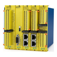
Overview of DNDS modules, power supply, mounting, connections, input modules, and cable adapters.
Lists DNDS module variants with monitoring and input/output functions.
Explains terminal purposes, LED meanings, and fault behavior.
Guide to setting divisor using DIP switches S1 and S2 for frequency adaptation.
Explanation of functions for switch positions 9 and 10 on S1 and S2.
Details output module configurations and their operating modes and display.
Specifies signal types, frequency, and output characteristics for measuring systems.
Covers monitoring, faults, LED indicators, and system reaction times.
Guidelines for unit installation, fuse protection, voltage connection, and setup.
Explains DIP switch settings, V9 configurations, and example setups.
Guides for selecting Vmax via terminals and choosing operating modes.
Covers measuring system connection, signal adjustment, and restart interlock.
Explains DIP switch functions for frequency setting, monitoring, and divisor settings.
Details the positive switching outputs O1 and O2 of the V7C module and their behavior.
Tables for selecting Vmax frequency using DIP switches and terminals for V7 modules.
Tables for selecting Vmax frequency using DIP switches and terminals for V7A/V7C.
Compares function modes (STOP, SH, R1, Fx, Dx) across different DNDS modules.
Defines the priority of control terminals (MT, R1, Dx, SH) for different operating modes.
Tables for selecting Vmax frequency using DIP switches and terminals for V7C modules.
Explains V7C terminal functions, MT/R1 usage, and control terminal priority.
Covers measuring system connection, signal adjustment, and restart interlock.
Explains DIP switch functions for frequency settings and input signal adjustment.
Details the positive switching outputs O1 and O2 of the V3C module and their behavior.
Compares function modes (STOP, SH, R1, Fx, Dx) across different DNDS modules.
Defines the priority of control terminals (MT, R1, Dx, SH) for different operating modes.
Tables for selecting Vmax frequency using DIP switches and terminals for 1R/1RG V1.
Tables for selecting Vmax frequency using DIP switches and terminals for 1R/1RG V2/V3C.
Details STOP and SPEED contacts, their functions, and behavior for monitoring.
Describes output usage, LED indicators, restart interlock, and connection diagrams.
Details STOP and SPEED1/SPEED2 contacts for standstill and speed monitoring.
Describes output usage, LED indicators, and delay time settings for SPEED2.
Illustrates output behavior with and without restart interlock and emergency stop function.
Diagrams illustrating parallel and serial connection methods for output modules.
Lists common faults like missing measuring system or open sensor connections.
Explains the function of outputs 13/14 and 23/24 for motion and standstill detection.
Details how outputs enable drive circuit splitting and control.
Describes faults like dark LEDs, missing systems, or contact issues.
Illustrates output behavior with and without restart interlock and speed monitoring.
Flowchart illustrating operating mode selection based on safety cover and speed conditions.
Provides dimensions, mounting details, and variant list for metal housings.
Provides dimensions, mounting details, and variant list for synthetic housings.
Details operating voltage, power consumption, safety contact assignments, and switching capabilities.
Provides data on contact lifespan under various load conditions (DC1, DC13, AC1, AC15) and a graph.
| Brand | DINA |
|---|---|
| Model | DNDS Modular Series |
| Category | Control Unit |
| Language | English |