Do you have a question about the DINA DNDSmodular and is the answer not in the manual?
Details on additional requirements for conformity.
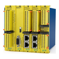
Lists the DNDS modular product components.
Identifies the notified body for testing and certification.
Provides contact information for the authorized person.
Describes the intended use of the DNDS modular system.
Presents key certification and safety data.
Visual representation for determining safety performance levels.
Instructions for adjusting modules within the rack.
Overview of available DNDS product variants.
Details on input module functionality and connection.
Information on connecting measuring systems via adapters.
Explanation of terminal assignments and their functions.
Describes the meaning of LED indicators.
Outlines how the system behaves during faults.
How to set the divisor using switches S1 and S2.
Explains the function of switch positions 9 and 10.
Shows connections for output modules.
Details the operational modes of output modules.
Specifies conditions for incremental measuring systems.
Covers basic operational principles and limitations.
Information on disabling monitoring functions.
Lists common faults and their causes.
Details system reaction times under various conditions.
Guidelines for installing the unit in a control cabinet.
Steps for commissioning the device.
Configuration for automatic operating mode.
Configuration for tool setting operating mode.
Configuration for semi-automatic operating mode.
Setting up the restart interlock function.
How to supply power to the measuring system.
Conditions for using a variable divisor.
How to select Vmax using D and F terminals.
Charts for selecting operating modes.
Details on outputs 01 and 02 for V7C module.
Frequency tables for V7 in tool setting/semi-auto modes.
Frequency tables for V7 in automatic mode.
Frequency tables for V7A/V7C.
Frequency tables for V7A/V7C in tool setting/semi-auto.
Frequency tables for V7A/V7C in automatic mode.
Charts illustrating function modes for V7A/V7C.
Priority order for control terminals on V7A/V7C.
Specific details for the new V7C version.
Frequency tables for V7C in tool setting/semi-auto.
Frequency tables for V7C in automatic mode.
Explains terminal functions specific to V7C.
Priority of control terminals for V7C.
How to set input frequency using S1.
Explains settings for S3 and S5 positions.
Details on S4 position configurations.
Information on V3C output behavior.
Charts for selecting function modes for V1, V2, V3C.
How to configure the 'No Monitoring' function.
Frequency tables for V1 in tool setting/semi-auto.
Vmax selection using D/F terminals for V1.
Frequency tables for V2/V3C.
Frequency tables for V2/V3C in tool setting/semi-auto.
Vmax selection tables for V2/V3C.
Describes contact outputs for PMG/PM/OM modules.
Functionality for monitoring standstill states.
Details on speed monitoring functions.
Explanation of LEDs on PMG/PM modules.
Output behavior without restart interlock.
Output behavior with restart interlock enabled.
Diagram for parallel output wiring.
Diagram for serial output wiring.
Describes contact outputs for VMG/VM modules.
Functionality for monitoring standstill states.
Details on speed monitoring functions.
How the emergency stop function works.
Wiring for parallel contact output.
Wiring for serial contact output.
Describes contact outputs for GMG/GM/GM V1 modules.
Functionality for monitoring standstill states.
Details on speed monitoring functions.
Lists common faults and their causes for these modules.
Wiring diagram for parallel output connections.
Wiring diagram for serial output connections.
Instructions for installing and removing modules.
Dimensions and weights for plastic housing variants.
Dimensions and weights for metal housing variants.
Specifies voltage, current, and power consumption.
Details on safety contact ratings and types.
Information on contact material and expected lifespan.
Ratings for switching inductive and non-inductive loads.
Details on mechanical life and cycles.
Covers insulation, temperature, and vibration.
Information on terminals, wiring, and housing.
Tables showing contact cycles under different loads.
| Category | Control Unit |
|---|---|
| Input Voltage | 24 VDC |
| Output Voltage | 24 VDC |
| Operating Temperature | -20°C to +60°C |
| Protection Class | IP20 |