DNDS Modular Original Betriebsanleitung Original Instruction Manual
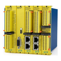
DNDS VMG und DNDS VM: Ausgangsmodule
DNDS VMG and DNDS VM: Output modules
Ausgangskontakte an
DNDS VM/ VMG
STOP: 13-14/ 23-24
offen bei Bewegung.
LED links ist dunkel,
geschlossen im Stillstand,
LED links ist grün.
Einsatz: Verriegelung einer
Schutzeinrichtung im
Automatikbetrieb
SPEED1: 33-34/ 43-44 öffnen
sofort bei V>Vmax.
LED rechts ist dunkel.
Einsatz: Start des Bremsvor-
gangs der Antriebe
SPEED2: 57-58/ 67-68
rückfallverzögert
Zeiteinstellung über DIP
Schalter am Modul.
Einsatz: Netztrennung
(Stopp Kategorie 1)
Achtung: im Fehlerfall kann die
Zeit verkürzt werden, bzw. die
Kontakte fallen sofort ab.
Alle Kontakte schließen wieder,
57-58/ 67-68 mit ≥ 250ms
Verzögerung wenn
an allen Eingangsmodulen
V< 90% von Vmax.
an den Klemmen E1, E2 und Q
liegen 24 VDC.
Q-Klemme kann spannungslos
werden nach Schließen der
Kontakte.
Rechte LED ist grün.
Contact outputs at
DNDS VM/ VMG
STOP: 13-14/ 23-24
open during movement.
LED left is dark.
Closed during standstill.
LED left is green.
Usage: interlocking of a safe
cover during the automatic
function mode.
SPEED1: 33-34/ 43-44 open
directly if V>Vmax.
LED right is dark.
Usage: start of the brake
action of the drives
SPEED2: 57-58/ 67-68
off delayed
time adjustment via DIP
switch on module
Usage: Net disconnection
(Stop category 1)
Warning: in case of fault the
delay time can
the contacts open at once.
All contacts close again
57-58/ 67-68 with ≥ 250ms
time delay if
at all input modules
V< 90% of Vmax.
Terminals E1, E2 and Q
connected to 24V DC.
Q-Terminal can be discon-
nected after the closing of all
contacts.
Right LED is green.
VM / VMG
0V
STOP
SPEED
UB
68
67
58
57
24
23
14
13
SPEED2
STOP
A1
33
34
43
44
SPEED1
A2
24V
DC
E1
E2
Q
A1
24V
DC
0.5A
A2 0V
DINA ELEKTRONIK
D-72649 WOLFSCHLUGEN
ID-No:10VM00
DNDS VM
1ZD7
US LISTED
IND.CONT.EQ
R
L
U
STOP
SPEED1
SPEED2
P.D. B300
DC1: 6A DC13: 4A
AC1: 6A AC15: 3A
B
G
-
P
R
U
F
Z
E
R
T
ET 13012
Sicherheit geprüft
tested safety
44
43
34
33
24
23
14
13
68
67
58
57
Q
E2
E1
A2
A1
A1
A1
A1
DNDS MODULAR OUTPUT MODULE
START
STOP
ON
SPEED
STOP
• SPEED1 und 2 können angesteuert werden über
E1, E2 und Q.
• Wird E1 oder E2 oder beide spannungslos, fallen die
Kontakte wie oben beschrieben in ihre Ruhestellung.
Siehe Diagramm unten.
• Bei nicht Verwendung dieser Funktion müssen alle
Klemmen ständig mit 24V DC verbunden sein.
(Drahtbrücke zu A1)
• SPEED1 and 2 can be controlled via the terminals E1,
E2 and Q.
• The contacts open as described above, if E1 or E2 or
both will be disconnected from 24V. See diagram
below.
• Close the terminals permanently to 24V, if this
function is not necessary. Wire connection to A1
13 23 33 43 57 67
14 24 34 44 58 68
L2
L1
13
23
33
43
57
67
14
24
34
44
58
68
L2
L1