DNDS Modular Original Betriebsanleitung Original Instruction Manual
Technical Data
B
B
SPEED 1 all output modules
SPEED 2 at GM V1, GMG V1, VM and VMG
Typical response time/ fall-back time of the contact output
Switching capability according to DIN EN 60947-4-1/DIN EN 60947-5-1
DC1: 24V/ 6A, DC13: 24V/ 4A, 0.1Hz
Switching capability according to DIN EN 60947-4-1/ EN 60947-5-1
AC1:250V/ 6A, AC15: 230V/ 3A, 0.1Hz
Sum current from all contact
Contact life DC13: 24V/ 1A
Contact life DC13: 24V/ 4A
Contact life AC15: 230V/ 0.5A
Contact life AC15: 230V/ 1A
Short-circuit strength
800A/safety fuse 6A gl
Surge voltage strength, use in pollution degree 2 Environment.
Internal unit fuse protection
Minimal 1,25A, Maximal: Conductor protection
Operating temperature DIN IEC 60068-2-3: -10 → + 60°C
Storage temperature DIN IEC 60068-2-3: -40→ + 85°C
High of the usage location
Vibration tolerance on all 3 levels
Sinus 10 – 55Hz, 0.35mm, 10 cycles, 1 Octave / min
Maximal frequency at the RJ45 connector
Maximal Frequency at the RJ45 connector
800Hz modulation, 10KHz carrier
Maximal frequency at IN1 and IN2
Temperature dependency of the trigger point
Core with crimp connector
Input terminals:1 x 1,0 mm
2
,
Output terminal: 1 x 1,5 mm
2
Spring load terminals, pluggable
Hosing synthetically material
Sheet steel, powder-coated
PVC, PC, PA / VO (UL94)
housing and terminals: IP20,
cabinet mounting with minimal protection IP 54
Contact durability
24V DC switching voltage: work days every year: 260, 8h every day
Switch current:
Switch cycles
1A
384
192
96
1A
15
7
3.6
4A
192
96
48
4A
1
0.5
0.25
6A
153
76
38
Years
5
10
20
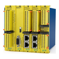
AC1: control of non-inductive or low inductive load AC voltage
AC15: control of inductive load AC voltage
DC1: control of non-inductive or low inductive load DC voltage
DC13: control of inductive load DC voltage
10
Schaltspiele / Cycles
Schaltstrom (A) / Switching current (A)
DC13
24V
AC15
230V
AC1
230V
DC1
24V
7
10
6
10
5
10
4
0.1 0.5 1.0 2.0 3.0 4.0 5
6
10