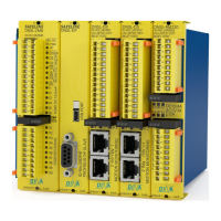
DNDS Modular Original Betriebsanleitung Original Instruction Manual
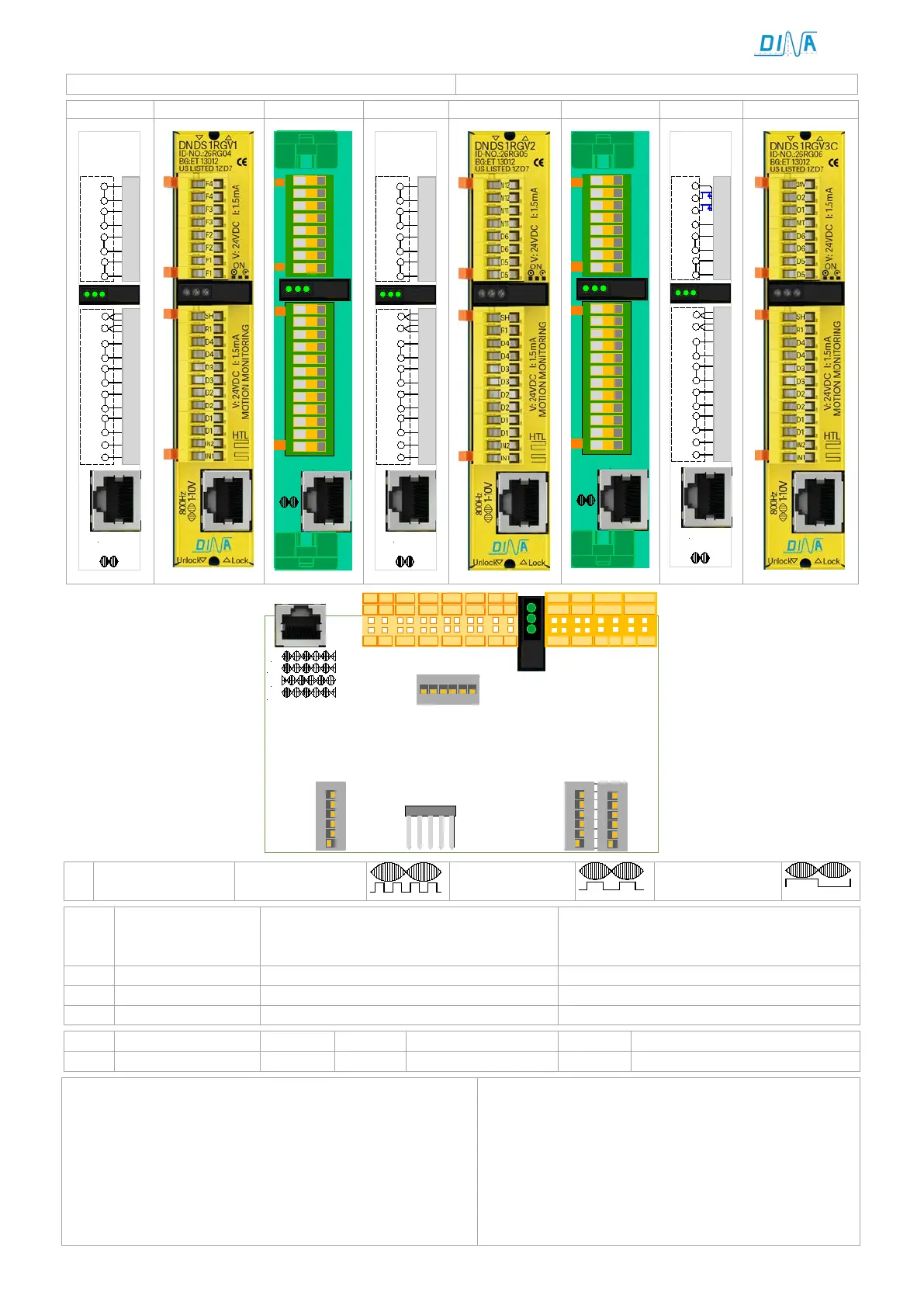
Eingangsmodul 1RG/ 1R /Resolver Messsystem
Input module 1RG/ 1R /Resolver measuring system
IN2
IN1
D1
D2
D3
D4
SH
R1
F1
F2
F3
F4
SPEED
UB
STOP
1R
1RG
1-10V
800Hz
F3
F2
F2
F1
F1
F3
F4
F4
1-10V
IN1
IN2
D1
D1
D2
D2
D3
D3
D4
D4
R1
SH
800Hz
SPEED
ON
STOP
IN2
IN1
D1
D2
D3
D4
SH
R1
D5
D6
M11
M12
SPEED
UB
STOP
1R
1RG
1-10V
800Hz
V2
1-10V
IN1
IN2
D1
D1
D2
D2
D3
D3
D4
D4
R1
SH
M11
D6
D6
D5
D5
M11
M12
M12
800Hz
SPEED
ON
STOP
IN2
IN1
D1
D2
D3
D4
SH
R1
D5
D6
MT
O1
SPEED
UB
STOP
1R
1RG
1-10V
800Hz
V3C
O2
24V
A
-A
B
-B
S4
V1/ V2 V3C
STOP
Pwr
SPEED
S3
S5
on
6
5
4
3
2
1
on
6
5
4
3
2
1
on
1234
56
IN1IN2 D1
D2
D3 D4
SH R1
IN1IN2 D1 D2 D3
D4 SH R1
IN1IN2 D1 D2 D3 D4
SH R1
F1
F2 F3 F4
D5 D6
M11 M12
D5 D6 MT O1
O2
24V
S1
on
6
5
4
3
2
1
Input frequency
Einstellung der Überwachungsfrequenz
für Halbautomatikbetrieb und
Einrichtbetrieb, Siehe Tabelle unten.
Adjustment of the monitoring Frequency
for semi-automatic function mode and
Tool-setting, see table down.
ON: Wiedereinschaltsperre aktiv
ON: restart interlock active
Off: Wiedereinschaltsperre inaktiv
Off: restart interlock inactive
Einstellung Eingangsamplitude
Adjustment input amplitude
• 2 positivschaltende Ausgänge O1 und O2.
• Spannung versorgt von O1, O2 über die Klemme 24V.
• Ausgang O1 schaltet ab bei Fehler am Messsystem oder
an IN1 und IN2. Im Normalfall ist O1 aktiv.
• Ausgang O2 schaltet ab bei V>Vmax, externem oder
internem Fehler. Im Normalbetrieb ist O2 aktiv.
O2 Funktion ist abhängig von der Wiedereinschaltsperre
2 positive switching outputs O1 and O2
O1, O2 are supplied via the terminal 24V.
Output O1 switches off if a failure at the measuring
system or at IN1 or IN2. Without failure is O1 active.
Output O2 is off if there is a V>Vmax, an external or
an internal failure. Without failure is O2 active.
The function of O2 is dependent of restart interlock.