DNDS Modular Original Betriebsanleitung Original Instruction Manual
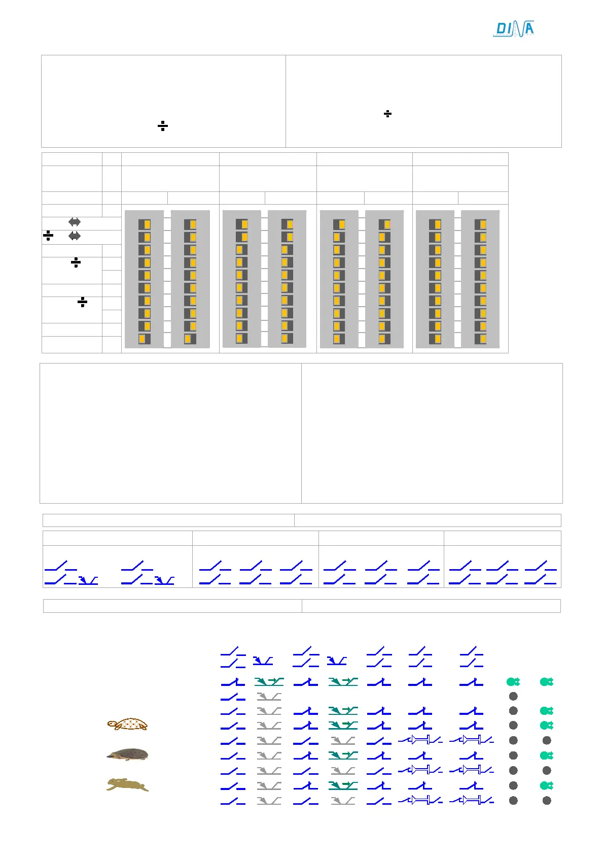
Einstellung des Teilers über S1 und S2, Position 1 - 8
• Der Teiler dient der Anpassung der Messsystem-
frequenz an den gewählten Frequenzwert am Ein-
gangsmodule.
• Frequenzwert in den nachstehenden Tabellen ist:
Messsystem Frequenz
(Teilereinstellung an S1 und S2 + 1)
Setting of the divisor via S1 and S2, switch on position 1 -
• The divisor has to adapt the frequency of the measuring
system to the selected frequency at the input module.
• Frequency value in the following tables is:
Measuring system
(divisor adjustment at S1 &S2+1)
2 x (1+1) 4
32+64+128)=512
32+64+128)=1024
not allowed
on
9
8
7
6
5
4
3
2
1
10
on
9
8
7
6
5
4
3
2
1
10
on
9
8
7
6
5
4
3
2
1
10
on
9
8
7
6
5
4
3
2
1
10
on
9
8
7
6
5
4
3
2
1
10
on
9
8
7
6
5
4
3
2
1
10
on
9
8
7
6
5
4
3
2
1
10
on
9
8
7
6
5
4
3
2
1
10
Einstellung
adjustment
Funktion der Schaltposition 9 und 10 an S1 und S2
S1, S2 P9 off: Teiler an (1 – 8) x 2
S1, S2 P9 on: Teiler an (1 – 8) x 4
S1, S2 P10 off:
Messsystemfrequenz < 50Hz unterdrückt.
Einkanalige Messsystemfrequenz < 800Hz ist
unterdrückt.
S1, S2 P10 on:
Messsystemfrequenz < 25Hz ist unterdrückt.
Einkanalige Messsystemfrequenz < 400Hz
ist unterdrückt.
Function of switch position 9 and 10 at S1 and S2
S1, S2 p9 off: divisor at (1 – 8) x 2.
S1, S2 p9 on: divisor at (1 – 8) x 4.
S1, S2 position 10 off:
measuring system frequency < 50Hz is muted
Single channel measuring system frequency < 800Hz
is muted.
S1, S2 p10 on:
measuring system frequency < 25Hz is muted.
Single channel measuring system frequency < 400Hz
is muted.
Ausgänge an den Ausgangsmodulen
Output at the output modules
Betriebsarten und Funktion der Ausgänge
Function modes and function of outputs
mode
SH, R1, D1-D6
STOP
SPEED