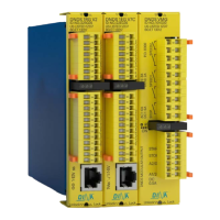
DNDS Modular Original Betriebsanleitung Original Instruction Manual
Einbau in einem Schaltschrank mit Schutzart von ≥IP54
The unit must be cabinet mounted (min. IP 54).
• Vor den Kontakten eine Sicherung (6A träge) schalten
• Die Reaktionszeit darf zu keiner Gefahr führen.
• Kupferleitung mit 60/75°C Temperaturbeständigkeit
• Angaben der technischen Daten unbedingt einhalten.
• Betriebsspannung an Klemmen A1 (+) und A2 (-)
• Use a fuse (6 A slow acting) in the output circuit.
• The reaction times must not be a reason for danger.
• Copper wiring that will withstand 60/75°C.
• Details in the “Technical Data” must be followed.
• Operating voltage on terminals A1 (24V and A2 (0V).
Automatikbetrieb bei Modulen mit D- und F-Klemmen
• Notwendige D-Klemmen mit 24V verbinden.
• Notwendige F-Klemmen über ein Steuerelement
an 24V
Automatikbetriebs bei Eingangsmodulen nur mit
D-Klemmen
• Notwendige D-Klemmen über ein Steuerelement an
24V
Einrichtbetrieb
• SH-Klemme über ein Steuerelement an 24V
Halbautomatikbetrieb
• R1-Klemme über ein Steuerelement an 24V
• Alle Steuerelemente müssen redundant ausgeführt
sein.
• Alle Abschaltpunkte müssen überprüft werden.
• Steuerleitungen in EMV sichere Kabelkanäle verlegen.
• Messsystem und Eingangsmodul über DINA
Kabeladapter verbinden bzw. 2 Sensoren an IN1 und
IN2 anschließen. Siehe Sensor Montage.
Automatic mode: modules with D- and F-Terminals
• Necessary D-Terminals directly to 24V DC
• Necessary F-Terminals connected to 24V via control
switch
Automatic mode with Input modules with D-Terminals
only
• Necessary D-Terminals connected to 24V via control
switch
Tool setting
• SH-Terminal connected to 24V via control switch
Semi-automatic mode
• R1-Terminal connected to 24V via control switch
• All control switches have to be mounted
redundantly.
• All switching off measuring points have to be
validated.
• For placing of control wires remark the EMC
requirements
• Connect the measuring system to the input module
via DINA cable adaptor respectively 2 sensors to
terminals IN1, IN2. See mounting of sensors.
Wiedereinschaltsperre, S4 Position 1 und 2 on
Der Ausgang SPEED am Ausgangsmodul bleibt ausge-
schaltet nach V>Vmax. Restart über 2s Spannungsunter-
brechung
Restart interlock, S4 position 1 and 2 on
The output SPEED on the output module remains
switched off after V>Vmax. Restart is after 2s power
off.
Bei einer Applikation mit max. 2 Achsen kann das Mess-
system aus dem DNDS versorgt werden. S4 Position 3
und 4 on.
For an application up to two axles the power can be
supplied from the DNDS. S4 position 3 and 4 on.
Variabler Teiler wird verwendet, wenn
Drehzahl des Automatikbetriebs bedeutend größer als
Drehzahl des Einrichtbetriebs
F- bzw. D-klemmen potentialfrei:
on Position 1 - 5+9 aktiv
F- bzw. D-Klemmen an 24V:
Alle on Positionen sind aktiv.
Variable divisor is to be used if
Speed of the automatic function mode significantly
greater than the speed of the tool setting mode.
F- or rather D-terminals potential free:
on position 1 - 5+9 active
F- or rather D-terminals connected to 24V:
All on positions are active

 Loading...