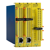
DNDS Modular Original Betriebsanleitung Original Instruction Manual
Betriebsarten und Funktion der Ausgänge
Function mode and function of the outputs
Gewählte maximale Geschwindigkeit
Öffnen sofort bei V>Vmax.
Öffnen bei V>Vmax nur wenn nach 0,5s V>90% von Vmax
Open at V>Vmax, only if after 0,5s V>90% of Vmax.
VM / VMG öffnen rückfallverzögert
VM / VMG open off delayed
Tool-setting function mode
semi-automatic function mode
Eingangsmodule mit F-Klemmen
input modules with F-Terminals
Eingangsmodule nur mit D-Klemmen
input modules with D-Terminals only
Bedingungen an das inkrementelle Messsystem
• Rechteck mit 0,5-5V oder Sin/Kos, 1Vss.
• Messsystem Frequenz ≤ 300KHz
• Hochohmigen Ausgängen im Störfall.
• 2 Spuren, 90° Phase, je Spur 2 antivalente Signale
• Keine synthetisch erzeugten Signale.
Achtung: Wellenbruch am Messsystem ist nicht
überwacht
Requirements of the incremental measuring system
• Signal rectangular 0.5-5V or Sin/Cos, 1Vpp
• Measuring system frequency ≤ 300KHz,
• High resistance outputs during malfunction.
• 2 tracks 90° phase, every track 2 antivalent signals
• Not synthetically generated signals
Attention: No monitoring of break on measuring
system axle
• Überwachung des absoluten Stillstands ist nicht mög-
lich.
• Die überwachte Frequenz im Stillstand ist nach
Teiler 5Hz.
• Bei Resolver wird auf Phasenänderung überwacht.
• Bei inkrementellem System:
überwachte Frequenz für Einrichten 10 – 20 > über-
wachte Frequenz für Stillstand.
• The monitoring of the Standstill on zero is not possi-
ble.
• The monitored standstill frequency is 5Hz after the
divisor.
• For resolver the change of the phase is monitored.
• For incremental system:
monitored frequency for tool-setting 10 – 20 > moni-
tored frequency for standstill.
Nicht benützte Überwachung
Für den nicht benötigten Überwachungssteckplatz ist ein
Brückenstecker bei DINA verfügbar.
Use a bridge connector for the not needed monitoring
position. Bridge connector can be ordered by DINA.
Bei Bedarf kann eine Überwachung durch prellfreies An-
legen des Eingangs IN2 an 24V stillgelegt werden.
In case if one monitoring system should be disabled,
this could be done by connecting the input IN2 to 24V.
• LED links und rechts ist dunkel.
Das Messsystem ist nicht vorhanden, Sensorfehler
• LED links oder rechts am Eingangsmodul blinkt mit 1Hz
Spur A oder B des Messsystems fehlt.
Sensor an IN1 oder IN2 ist fehlerhaft oder fehlt.
• LED rechts geht im Stillstand aus.
Speicherung von früheren V>Vmax. Quit: 2s Pwr aus.
• LED links oder rechts am Eingangsmodul blinkt mit 2Hz
DNDS Störung oder Störung durch unsachgemäß ver-
legte Signalleitungen. Quit: 2s Pwr aus.
• Dark LED left and right
No measuring system exists. Sensor failure
• LED left or right at input module is flashing with 1Hz
Track A or B of measuring system is missing.
Sensor at IN1 or IN2 is defect or is missing.
• LED right goes out during standstill.
Memory of previous V>Vmax. Quit: 2s Pwr off.
• LED left or right at an input module is flashing in 2Hz
DNDS internal error or fault by improperly installed
external signal lines. Quit: 2s Pwr off.
Die Summe der Reaktionszeit ergibt sich aus:
• Reaktionszeit der Überwachung
• Abfallzeit der Ausgangsrelais (<20ms)
• Abschaltzeiten der externen Schaltelemente.
• Reaktionszeit der Überwachung sinkt ab mit der Zu-
nahme der überwachten Drehzahl. Bei 5Hz=200ms,
1000Hz=1ms
The total reaction time is the sum of:
• Reaction time of the monitoring
• Fall time of the output relay (<20ms)
• Switch off time of any external switching devices.
• The reaction time of the monitoring decreases with
the increasing of the monitored speed. 5Hz=200ms,
1000Hz=1ms

 Loading...