DNDS Modular Original Betriebsanleitung Original Instruction Manual
• DNDS arbeitet mit einer Betriebsspannung von 24V DC.
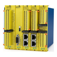
• Das Gerät ist zur Montage auf einer 35mm Hutschiene.
• Die Funktionsmodule sind in steckbar einem Rack.
• Bis zu 8 Eingangsmodule und ein Ausgangsmodul sind
in einem Rack möglich.
• Alle Anschlüsse sind steckbare Federkraftklemmen.
• DNDS works with24V DC power supply.
• The unit is mountable on a 35mm DIN rail.
• The function modules are pluggable in a rack.
• Up to 8 input modules and one output module are
possible in a rack.
• All connections are pluggable spring loaded
clamps.
• Das DNDS dient der sicheren Überwachung einer
rotierenden bzw. linearen Bewegung.
• Die Bewegungserfassung einer Achse erfolgt
über ein inkrementelles oder Resolver Messsys-
tem bzw. 2 PNP Sensoren an IN1 und IN2.
• Das Messsystem wird über den Kabeladapter
DNDA an DNDS angeschlossen.
• Die PNP Sensoren werden über die Klemmen IN1
und IN2 am Eingangsmodule angeschlossen.
• Die Montage der Sensoren muss sicherstellen,
dass im Stillstand mindestens ein Sensor aktiv
ist.
• Statusanzeige über LED
• Auswahl der max. Drehzahlen erfolgt über DIP
Schalter und Klemmen.
Zahnrad
Gear
Sensor
Sensor
IN1IN2
• The DNDS is designed for safe monitoring of
rotary respectively linear motion.
• The movement detection of an axle happens
via an incremental or resolver measuring
system respectively 2 PNP sensors at IN1
and IN2.
• The measuring system is to connect to the
DNDS using the cable adapter DNDA
• The PNP sensors are to connect via the ter-
minals IN1 and IN2 at the input modules.
• The mounting of the sensors has to enable
at least one active sensor during standstill.
• Status indicators via LED
• Setting of the maximal speeds happens via
DIP switches and terminals.
Zur Anbindung der Überwachung an das Achsenmess-
system sind verschiedene Kabeladapter mit verschiede-
nen Steckverbindungen lieferbar. Siehe Betriebsanlei-
tung „Kabeladapter“.
To connect the monitoring with the axle feedback
measuring system different cable adapters with differ-
ent connectors are available. See instruction manual
“Cable adapter”.
DNDA 9/8
DNDA 15/8
DNDA 25/8