DNDS Modular Original Betriebsanleitung Original Instruction Manual
DNDS GMG, GM/ DNDS GMG, GM V1: Ausgangsmodule
DNDS GMG, GM/ DNDS GMG, GM V1: Output modules
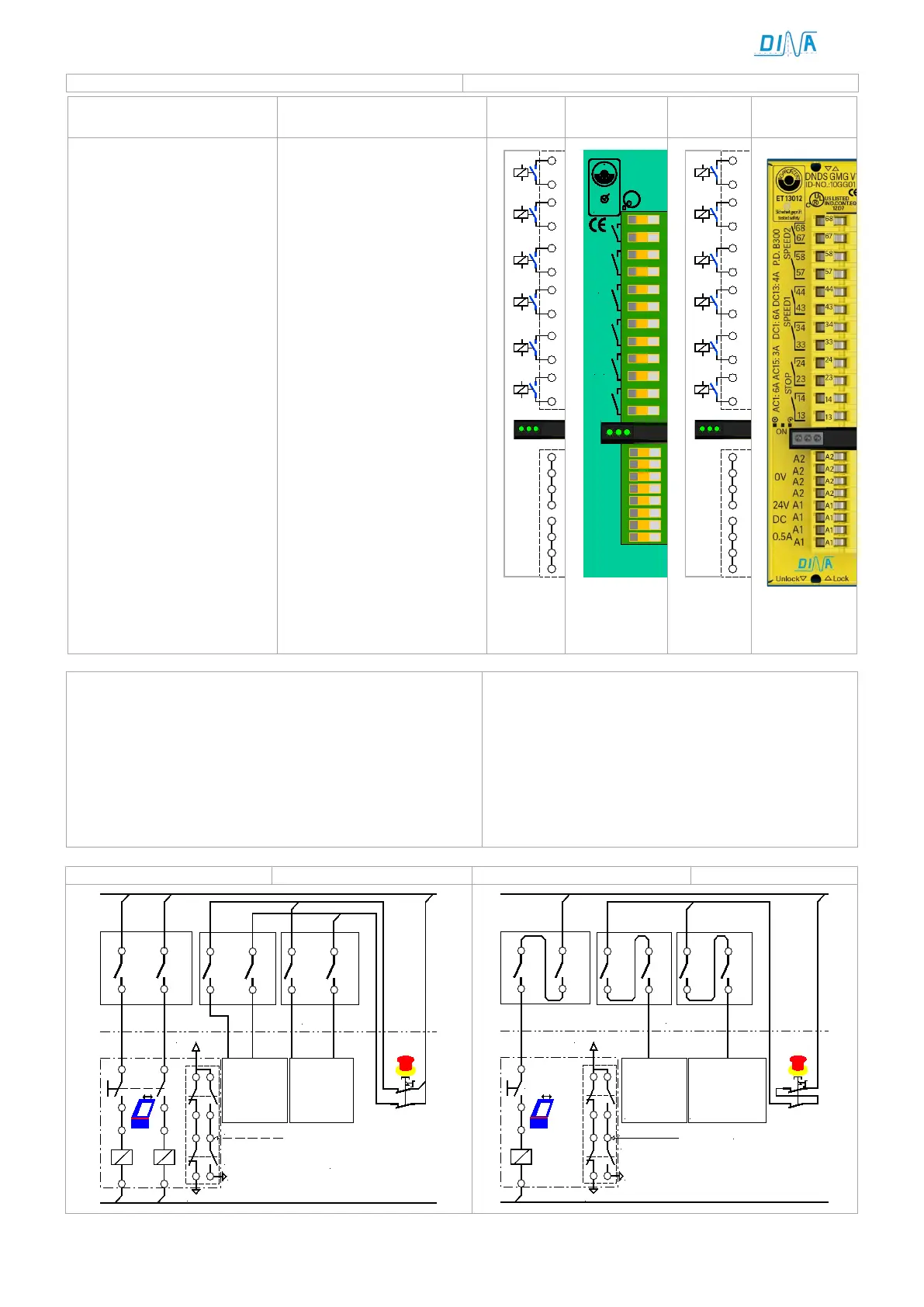
Ausgangskontakte an
DNDS GMG/ GM
Contact outputs at
DNDS GMG/ GM
GM
GMG V1
GMG V1
• Stillstandsüberwachung
•
STOP: 13-14/ 23-24
offen bei Bewegung, LED
links dunkel,
geschlossen im Stillstand,
LED links grün.
Einsatz: Verriegelung einer
Schutzeinrichtung im Au-
tomatikbetrieb
Drehzahlüberwachung
SPEED1: 33-34/ 43-44 öff-
nen sofort bei V>Vmax.
LED rechts ist dunkel.
schließen sofort bei V<
90% von Vmax, LED rechts
ist grün.
Einsatz: Start des Brems-
vorgangs der
Antriebe
Siehe auch Wiederein-
schaltsperre.
SPEED2: 53-54/ 63-64
Siehe SPEED 1.
Dieses Modul ermöglicht
die Teilung des Antriebs-
verbunds in zwei Kreisen.
• Standstill monitoring
•
STOP: 13-14/ 23-24
open during movement,
LED left is dark
closed during standstill,
LED left is green.
Usage: interlocking of a
safe cover during the au-
tomatic function mode.
Speed monitoring
SPEED1: 33-34/ 43-44 open
directly if
V>Vmax. LED right is dark.
SPEED1: 33-34/ 43-
directly if
V< 90% of Vmax, LED right
is green.
Usage: start of the brake
action of the drives
See also restart interlock.
SPEED2: 53-54/ 63-64
See SPEED1
This output module ena-
bles the splitting of the
drive circuit in two circuits.
GM / GMG
V1
0V
STOP
SPEED
UB
68
67
58
57
24
23
14
13
SPEED2
STOP
A1
33
34
43
44
SPEED1
A2
24V
DC
A1
24V
DC
0.5A
A2
0V
DINA ELEKTRONIK
D-72649 WOLFSCHLUGEN
ID-No:10GM0
DNDS GM
1ZD7
US LISTED
IND.CONT.EQ
R
L
U
STOP
SPEED1
SPEED2
P.D. B300
DC1: 6A DC13: 4A
AC1: 6A AC15: 3A
B
G
-
P
R
U
F
Z
E
R
T
ET 13012
Sicherheit geprüft
tested safety
44
43
34
33
24
23
14
13
64
63
54
53
A2
A2
A2
A2
A1
A1
A1
A1
DNDS MODULAR OUTPUT MODULE
ON
SPEED
STOP
GM / GMG
V1
0V
STOP
SPEED
UB
68
67
58
57
24
23
14
13
SPEED2
STOP
A1
33
34
43
44
SPEED1
A2
24V
DC
LED links und rechts am Ein- und Ausgangsmodul dunkel.
Ursachen:
Kein Messsystem.
Sensorfehler an Klemme IN1, IN2
LED links und rechts auf dem Ausgangsmodul blinken kurz
Ursachen:
Ein Kontakt schließt oder öffnet nicht.
LED right and left at the in- and output module dark.
Reason:
No measuring system
Sensor failure at the terminal IN1, IN2
LED left and right on the output module flash short:
Reason:
A contact does not close or open.
NOT-HALT
Kreis 1
44
43
34
33
13
14
23
24
L1
L2
DNDS
11
13
12
14
21
23
22
24
64
63
54
53
24V DC
NOT-HALT
Kreis 2
STOP
SPEED1
SPEED2
DNDS
CNC
Emergency
stop circuit 1
Emergency
stop circuit 2
Schutztürschalter
Protection cover
switch
Quit
Tür
entriegeln
Cover
unlock
NOT-HALT
Kreis 1
44
43
34
33
13
14
23
24
STOP
SPEED1
L1
L2
Tür entriegeln
DNDS
DNDS
Quit
Schutztürschalter
11
13
12
14
21 23
22
24
64
63
54
53
SPEED2
24V DC
CNC
N
OT-HALT
Kreis 2
Emergency
stop circuit 1
Emergency
stop circuit 2
Protection cover switch
Cover unlock