Original Betriebsanleitung Original Instruction Manual
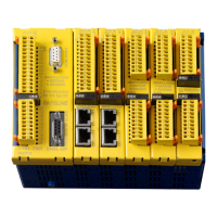
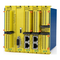
Module
Klemme Drehzahlüberwachung Speed monitoring
DNSL- ID
IDID
ID-
--
-No:
No:No:
No:
Terminal
alle/all
P1, P2
digitale Eingänge für Sicherheitsfunktionen
24V DC zur Versorgung der Ausgänge
digital inputs for safety functions
24V DC to supply the outputs
DS
24DS07
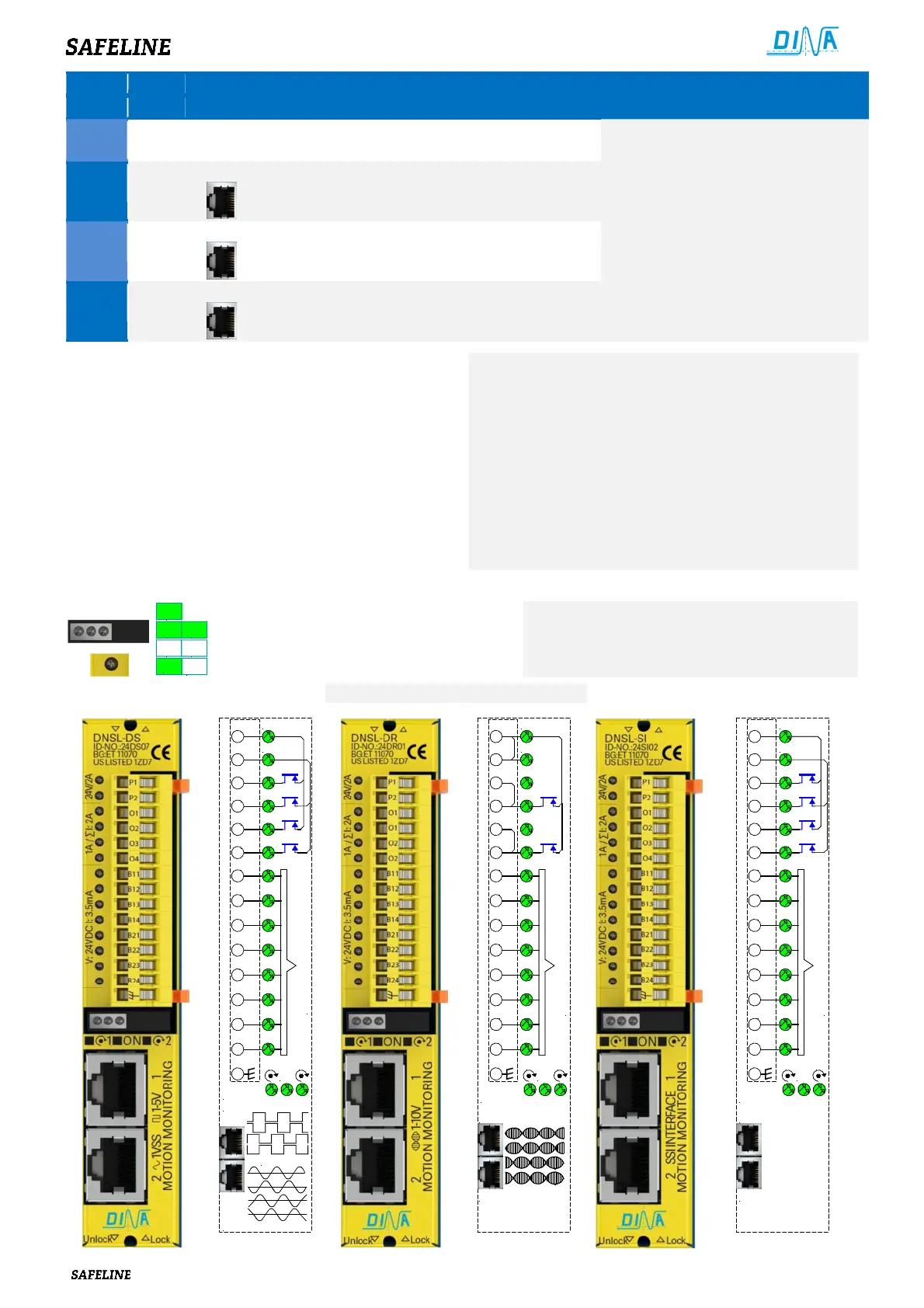
Ausgänge, 4 Takt oder 2 sichere Ausgänge
2 sichere Drehzahlüberwachungen über 2 RJ45
Buchsen für 2 inkrementelle Messsysteme
outputs, 4 clock or 2 safe outputs
2 safe speed monitoring via 2 RJ45 plug
for incremental measurement systems
DR
24DR01
Ausgänge, 2 Takt oder 1 sicherer Ausgang
2 sichere Drehzahlüberwachungen über
2 RJ45 Buchsen für 2 Resolver Messsysteme
outputs, 2 clock or 1 safe output
2 safe speed monitoring via 2 RJ45 plug
for 2 resolver measurement systems
SI
24SI02
Ausgänge, 4 Takt oder 2 sichere
2 Drehzahlüberwachungen über 2 RJ45 Buchsen
für 2 SSI Interface Messsysteme
outputs, 4 clock or 2 safe outputs
2 safe speed monitoring via 2 RJ45 plug
for SSI interface measurement systems
Die Module ermöglichen die Überwachung von Stillstand,
Drehzahl, Position, Richtung und Bremsfunktion an zwei
Achsen.
• Die Drehzahl kann in verschiedenen Betriebsarten
überwacht werden.
• Die Halbleiterausgänge sind überlast- und
kurzschluss-sicher.
• Die Betriebsspannung erfolgt über die Klemmen A1 und
A2 am Zentralmodul.
• Eine Klemme für die lokale Erdung der Anschlussbuchsen
des Messsystems ist ebenfalls vorgesehen.
• The modules enable the monitoring of standstill,
speed, position, direction and brake function of tow
axles.
• The speed can be monitored in different function
modes.
• The semi-conductor outputs at the modules are
overload and short-circuit-proof.
• The power supply (24V DC) happens via the terminals
A1 and A2 at the central module.
• A terminal for local grounding of the measuring system
sockets is also available.
Anzeige Display
3 1 2
2 3
2
3
Interne
Spannung
• Messsysteme OK, Ist-Drehzahl < Max
• Keine Messsysteme / Ist-Drehzahl > Max.
• Status der Ein-, Ausgänge und UB
• Internal voltage
• Measuring systems OK, actual speed < max.
• No Measuring systems, actual speed > max
•
Status of in-, and outputs and power supply
DNSL-DS Schema DNSL-DR Schema DNSL-SI Schema
DS
ON
Encoder 1
Encoder 2
P1
P2
24V DC
24V DC
O1
O2
O3
O4
B11
B12
B13
B14
B21
B22
B23
B24
1 2
oder / or
Eingänge/ Inputs
DR
Resolver 2
21
B24
B23
B22
B21
B14
B13
B12
B11
O2
O1
24V DC
24V DC
P2
P1
Resolver 1
ON
O2
O1
Eingänge/ Inputs
SI
ON
SSI 1
SSI 2
P1
P2
24V DC
24V DC
O1
O2
O3
O4
B11
B12
B13
B14
B21
B22
B23
B24
1 2
Eingänge/ Inputs
 Loading...