Original Betriebsanleitung Original Instruction Manual
Module
ModuleModule
Module
Klemme
ID-No:
ID-No:
Terminal Beschreibung Description
alle
allealle
alle al
alal
all
ll
l
A1/ A2
I1-I6
Betriebsspannung 24V DC für alle Module in
der Applikation
sichere Eingänge für Sicherheitsfunktionen
Power supply 24V DC for all
modules in the application
safe inputs for safety functions
ZM
ZMZM
ZM
24ZM20
24ZM30
O6, O7
sichere Halbleiterausgänge
1 sicherer oder 2 Takt Ausgänge
1 safe or 2 clock outputs
ZMA
ZMAZMA
ZMA
24ZA20
24ZA30
O2, O3
Anschluss für Potentiometer
sichere Halbleiterausgänge
Connection for Potentiometer
safe semi-conductor outputs
ZMK
ZMKZMK
ZMK
24ZK20
24ZK30
13-14/23-24
Kontaktausgang, 2 sichere NO Kontakte
contact output, 2 safe NO contacts
ZMB
ZMBZMB
ZMB
CP
CPCP
CP
UP
UPUP
UP
24ZB40
24CP40
24UP41
2: I13/I14
I11-I20
O2, O3
13-14/23-24
2 sichere Drehzahlüberwachungen
Sensor mit 24V Signalen
sichere Eingänge für Sicherheitsfunktionen
sichere Halbleiterausgänge
Kontaktausgang, 2 sichere NO Kontakte
Sensor with 24V signals
safe inputs for safety functions
safe semi-conductor outputs
contact output, 2 safe NO contacts
ZMR
ZMRZMR
ZMR
CP
CPCP
CP
UP
UPUP
UP
KM
KMKM
KM
24ZR40
24CP40
24UP41
24KM01
2: I13/I14
I11-I20
O2-O5
O6, O7
O1-O4
13/14, 23/24
33/34, 43/44
53/54, 63/64
73/74, 83/84
2 sichere Drehzahlüberwachungen
Sensor mit 24V Signalen
sichere Eingänge für Sicherheitsfunktionen
sichere Halbleiterausgänge
Schalt- oder Taktausgänge
Ausgangserweiterung nur in Verbindung
mit DNSL-ZMR
Diagnose Kontaktausgänge
Sichere Kontaktausgänge
Sensor with 24V signals
safe inputs for safety functions
safe semi-conductor outputs
switching or clock outputs
Output extension, possible with
DNSL-ZMR only
Diagnostics contact outputs
Safe contact outputs
ZMT
ZMTZMT
ZMT
CP
CPCP
CP
UP
UPUP
UP
24ZT40
24CP40
24UP41
2: I13/I14
I11-I15
I16-I20
O2, O3
13-14/23-24
sichere Drehzahlüberwachungen
Sensor mit 24V Signalen
sichere Eingänge für Sicherheitsfunktionen
sichere Eingänge für Schaltmattenfunktion
Fa. Mayser Typ TS/W1 und TS/ BK1
2 sichere Halbleiterausgänge
Kontaktausgang, 2 sichere Kontakte
Sensor with 24V signals
safe inputs for safety functions
safe inputs for shut mat function
co. Mayser type TS/W1 und TS/ BK1
safe semi-conductor outputs
contact output, 2 safe NO contacts
Das Interface USB bzw. V24 ist für Datentransfer zwischen
SAFELINE und einem PC sowie Diagnoseaufgaben.
• Bei USB-Versionen können Daten wie Applikation, Designer
auf einem internen Speichermedium hinterlegt werden.
Das Medium arbeitet als Laufwerk.
• Bei Einsatz von DNSL-ZMB, ZMR oder ZMT befindet sich
das Interface auf einem separaten Modul. Es kann auch am
eingesetzten Feldbus integriert sein.
Verhalten bei Störung
Verhalten bei StörungVerhalten bei Störung
Verhalten bei Störung:
• Ausgang O1 am Zentralmodul schaltet ab.
• Abhilfe: Kontrolle der Verdrahtung und Konfiguration.
•
Unterbrechung der Betriebsspannung löscht den Fehler.
The interface USB respectively V24 is used to transfer data
between the PC and SAFELINE and for diagnostics duties.
• The user application and Designer can be stored on an
internal memory medium if the USB PORT is used.
The memory medium works as a drive.
• The interface is mounted at a separate module if DNSL-ZMB,
ZMR or ZMT is used. The interface can be also mounted at
the used field bus.
Behavior with errors
Behavior with errorsBehavior with errors
Behavior with errors:
• Output O1 at the central module is switching off.
• Correction Inspection of the wiring and assembly
•
Switching off and on of the power clears the errors.
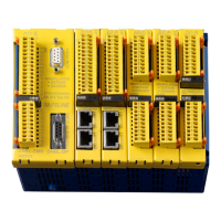
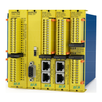
Zentralmodule
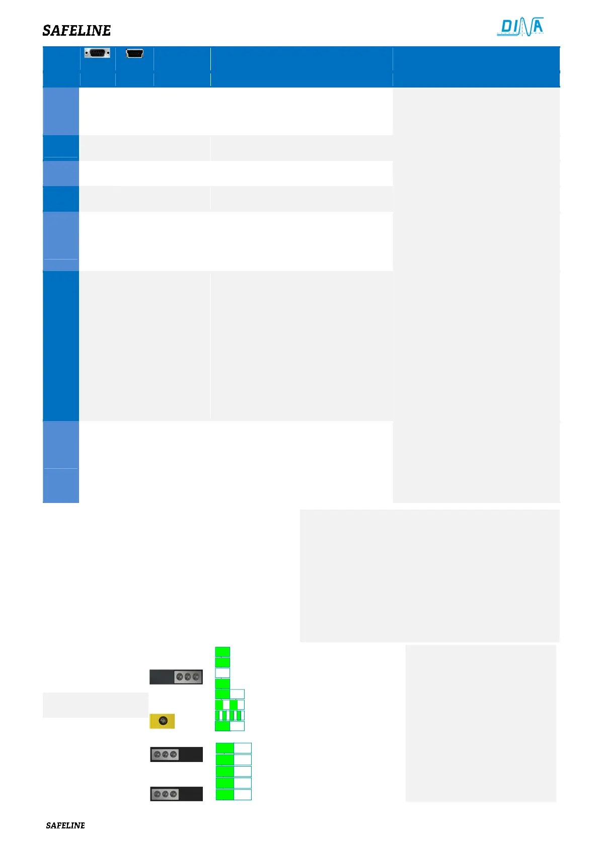
Anzeige
Central modules
Display
2 1 3
1
2
2
3
3 3
3
3
on
off
• Interne Spannung
• Master OK
• Daten Transfer
• Slave OK, Applikation validiert
• Applikation nicht validiert
• SLOK OFF
• Daten Transfer/ Diagnose
•
• Internal voltage
• Master OK
• Data transfer
• Slave OK, Application validated
• Application not validated
• SLOK OFF
• Data transfer/ Diagnostics
•
DNSL-KM
Anzeige / Display
2 Pwr 1
4 Pwr 3
1
2
3
• Interne Spannung
• 13/14, 23/24 Ein-AUS
• 33/34, 43/44 Ein-AUS
• 53/54, 63/64 Ein-AUS
•
• Internal voltage
• 13/14, 23/24 ON-OFF
• 33/34, 43/44 ON-OFF
• 53/54, 63/64 ON-OFF
•
 Loading...