4. Descripción del aparato
4.3 Descripción del aparato
DIX FDE-IB (LWL) 100 L
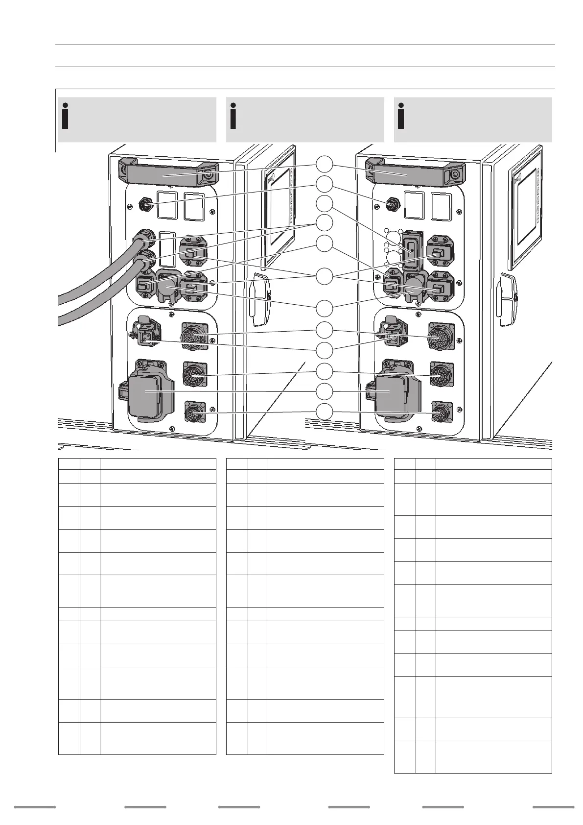
4.3.2 Vista trasera
Pos. Descripción
1 Asa de transporte trasera
2 X18
Conexión de fuente de corriente
de la hilo caliente
Bus CAN (opcional)
3
INTERBUS 9 polos (H)
conectores de cable de cobre
4
INTERBUS bra óptica de
salida
5 X17
Monitoring (opcional)
RJ 45
6
X15.1
X15.2
Tensión del BUS:
1 x 24VCC
1 x 24VCC conectado
5 polos (M)
7 X24 Interfaz USB
8 X7
Interfaz analógica
28 polos (H)
9 X12
Tensión de red
5 polos (M)
10 X3
Unidad de control
Unidad de arrastre frontal
FD 100 LS(-WB)
23 polos (H)
11 X11
Integración en el circuito de protección
6 polos (M)
12 X5
Unidad de control
Devanador de hilo WD 300
12 polos (H)
(M = conector macho / H = conector hembra)
I
N
F
O
La interfaz INTERBUS se puede pedir con
conexión de cable de cobre (g. derecha DIX
FDE-IB 100 L) o con conexión para conductor de
bra óptica (g. izquierda DIX FDE-IB LWL 100 L).
4. Device description
4.3 Device description
DIX FDE-IB (LWL) 100 L
4.3.2 Rear view
Item Description
1 Rear handle
2 X18
Connection
hot wire power source
CAN-Bus (optional)
3
INTERBUS 9 pin (F)
copper wire connection
4
INTERBUS outgoing
glass ber cable
5 X17
Monitoring (optional)
RJ 45
6
X15.1
X15.2
BUS voltage 1 x 24 VDC
1 x 24 VDC
switched
5 pin (M)
7 X24 USB interface
8 X7
Analog interface
28 pin (F)
9 X12
Supply voltage
5 pin (M)
10 X3
Control unit
FD 100 LS(-WB) front drive
23 pin (F)
11 X11
Integration into protective circuit
6 pin (M)
12 X5
Control unit
WD 300 wire feeder
12 pin (F)
(M = male connector / F = female connector)
I
N
F
O
The INTERBUS interface can be ordered
with copper cable connection (Fig. right DIX
FDE-IB 100 L) or with optical waveguide
connection (Fig. left DIX FDE-IB LWL 100 L).
4. Gerätebeschreibung
4.3 Gerätebeschreibung
DIX FDE-IB (LWL) 100 L
4.3.2 Rückansicht
Pos. Beschreibung
1 Hinterer Tragegriff
2 X18
Anschluss
Heißdrahtstromquelle
CAN-Bus (optional)
3
INTERBUS 9 pol. (W)
Kupferkabelanschluss
4
INTERBUS ausgeführte
Lichtwellenleiter
5 X17
Monitoring (optional)
RJ 45
6
X15.1
X15.2
BUS-Spannung: 1 x 24VDC
1 x 24VDC geschaltet
5 pol. (M)
7 X24 USB Schnittstelle
8 X7
Analoge Schnittstelle
28 pol. (W)
9 X12
Netzspannung
5 pol. (M)
10 X3
Steuerung
Frontantrieb FD 100 LS(-WB)
23 pol. (W)
11 X11
Einbindung in den Schutzkreis
6 pol. (M)
12 X5
Steuerung
Drahtvorschub WD 300
12 pol. (W)
(M = männlicher Anschluss / W = weiblicher Anschluss)
I
N
F
O
Die INTERBUS-Schnittstelle kann mit Kupfer-
kabelanschluss (Abb. rechts DIX FDE-IB 100 L)
oder mit Lichtwellenleiteranschluss (Abb. links
DIX FDE-IB LWL 100 L) bestellt werden.
SchweiSSen welding
weldingSoldadura SchweiSSen
31
:
:
:
:
:
:
1
2
10
8
5
7
12
11
4
9
3
7

 Loading...