5.1 Conexión de la unidad de control
5.1.2 Conexión de FDE-DN 100 L
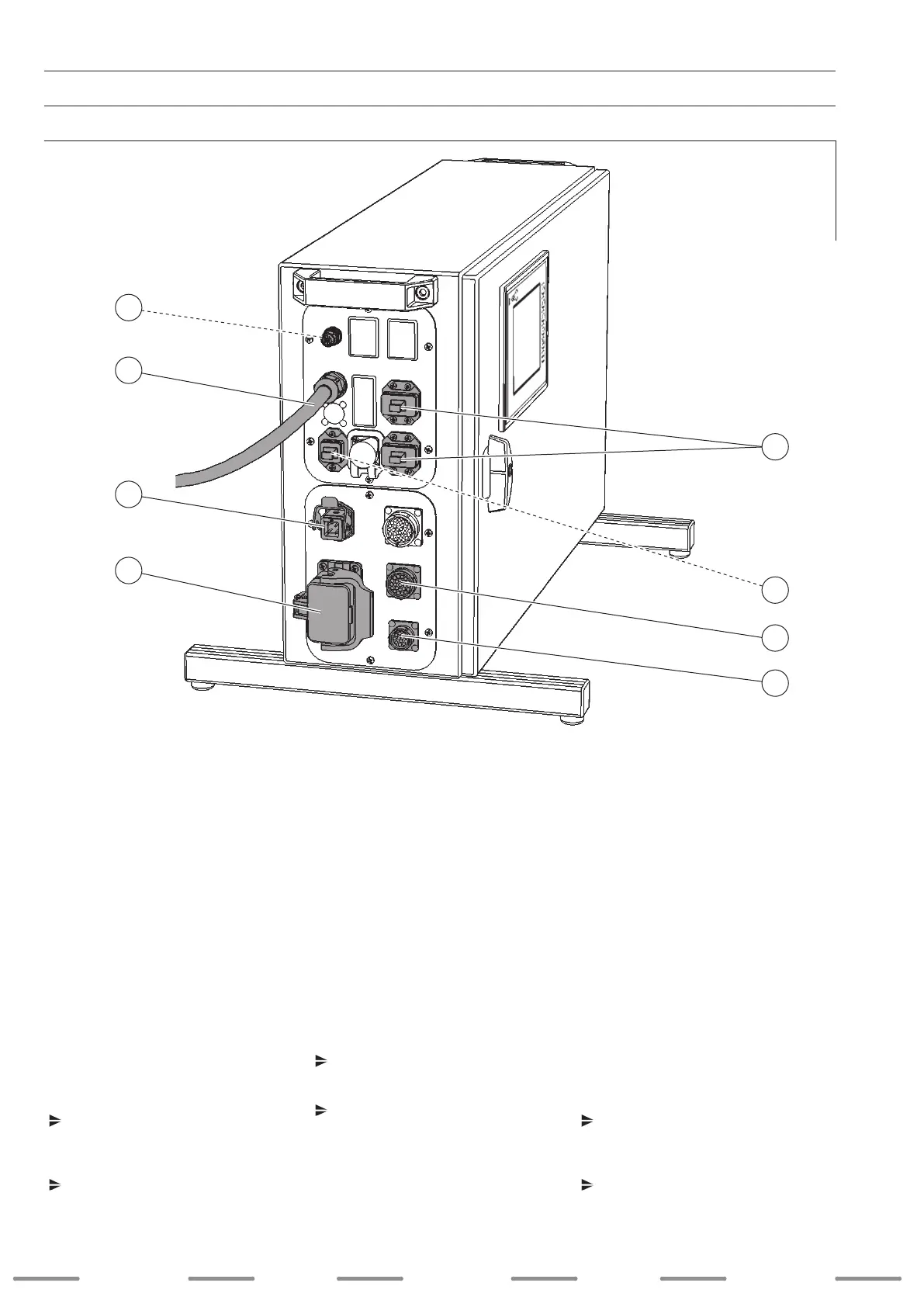
1. Conecte el cable del circuito de protección
en la posición 4 y je el enchufe macho con
el cierre a presión.
2. Lleve el cable del DEVICENET a la posición
2 y una el cable con el DEVICENET
(para la asignación de pines
véase esquemas de conexiones
anexo A, página 137 para 230V
CA y
anexo B, página 147 para 115VCA).
3. Conecte el cable de la alimentación de
tensión del BUS en la posición 5.
4. Conecte el cable control de la unidad de
arrastre frontal en la posición 7 y apriete la
tuerca de unión.
5. Conecte el cable control del devanador
de hilo en la posición 8 y apriete la tuerca
de unión.
6. Conecte el cable de tensión de red en la
posición 3 y je el enchufe macho con el
cierre a presión.
Conexiones opcionales
Conecte la fuente de corriente de hilo
caliente DIX PI 270 HW con un cable de
bus CAN en la posición 1 y apriete la tuerca
de unión.
Conecte el cable de monitorización en la
posición 6.
5. Puesta en marcha
5.1 Connecting the control unit
5.1.2 Connecting the FDE-DN 100 L
1. Connect the protective circuit lead to item 4
and x the plug with the stirrup lock.
2. Route the wire of the DEVICE-
NET through item 2 and connect the
leads with the DEVICENET
(for pin assignment, see circuit diagrams
Appendix A page 137 for 230 V
AC and
Appendix B page 147 for 115 VAC).
3. Connect the wire of the BUS voltage supply
to item 5.
4. Connect the control wire of the front drive
to item 7 and tighten the cap nut.
5. Connect the control wire of the wire feed to
item 8 and tighten the cap nut.
6. Connect the supply voltage lead to item 3
and x the plug with the stirrup lock.
Optional connections
Connect the hot wire power source
DIX PI 270 HW to a CAN-bus lead at
Pos. 1 and tighten the cap nut.
Connect the monitoring lead to item 6.
5. Startup
5.1 Steuerung anschließen
5.1.2 FDE-DN 100 L anschließen
1. Schließen Sie die Schutzkreisleitung an
Pos. 4 an und xieren den Stecker mit dem
Spannbügel.
2. Führen Sie die Leitung des DEVICE-
NET an Pos. 2 durch und verbinden die
Leitung mit dem DEVICENET
(Pinbelegung siehe Schaltpläne
Anhang A Seite 137 für 230V
AC und
Anhang B Seite 147 für 115VAC).
3. Schließen Sie die Leitung der BUS-Span-
nungsversorgung an Pos. 5 an.
4. Schließen Sie die Steuerleitung des Front-
antriebs an Pos. 7 an und schrauben die
Überwurfmutter fest.
5. Schließen Sie die Steuerleitung des
Drahtvorschubs an Pos. 8 an und schrau-
ben die Überwurfmutter fest.
6. Schließen Sie die Netzspannungsleitung
an Pos. 3 an und xieren den Stecker mit
dem Spannbügel.
Optionale Anschlüsse
Schließen Sie die Heißdrahtstromquelle
DIX PI 270 HW mit einer CAN-Bus-Leitung
an Pos. 1 an und schrauben die Überwurf-
mutter fest.
Schließen Sie die Monitoring-Leitung an
Pos. 6 an.
5. Inbetriebnahme
SchweiSSen welding
weldingSoldadura SchweiSSen
40
: :
: :
1
6
3
4
8
7
2
: :
5

 Loading...