4. Descripción del aparato
4.4 Descripción del aparato
DIX FDE-PB 100 L
4.4.2 Vista trasera
Pos. Discriptión
1 Asa de transporte trasera
2 X18
Conexión de fuente de corriente
de la hilo caliente
Bus CAN (opcional)
3 X16
PROFIBUS
9 polos (H)
4 X17
Monitoring (opcional)
RJ 45
5 X12
Tensión de red
5 polos (M)
6 X11
Integración en el circuito de
protección 6 polos (M)
7
X15.1
X15.2
Tensión del BUS:
1 x 24VCC
1 x 24VCC conectado
5 polos (M)
8 X24 Interfaz USB
9 X7
Interfaz analógica
28 polos (H)
10 X3
Unidad de control
Unidad de arrastre frontal
FD 100 LS(-WB)
23 polos (H)
11 X5
Unidad de control
Devanador de hilo WD 300
12 polos (H)
(M = conector macho / H = conector hembra)
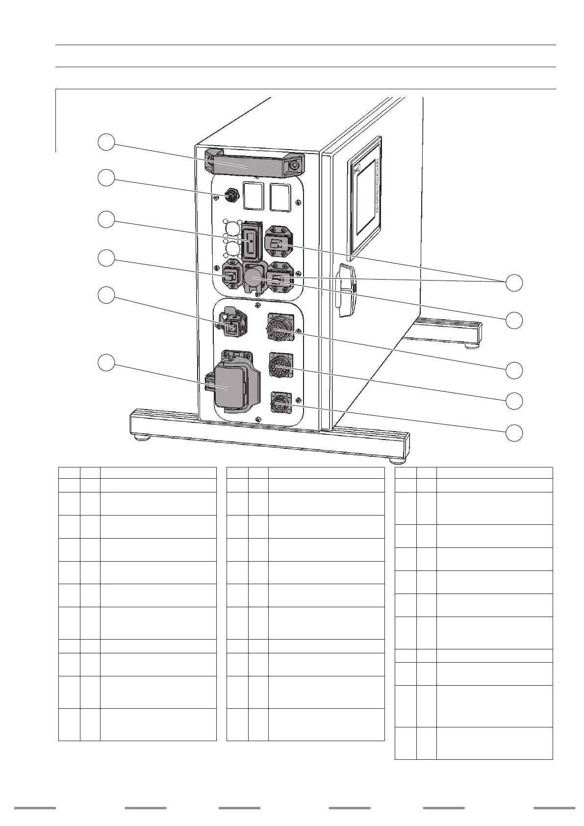
4. Device description
4.4 Device description
DIX FDE-PB 100 L
4.4.2 Rear view
Item Description
1 Rear handle
2 X18
Connection
hot wire power source
CAN-Bus (optional)
3 X16
PROFIBUS
9 pin (F)
4 X17
Monitoring (optional)
RJ 45
5 X12
Supply voltage
5 pin (M)
6 X11
Integration into protective circuit
6 pin (M)
7
X15.1
X15.2
BUS voltage 1 x 24 VDC
1 x 24 VDC
switched
5 pin (M)
8 X24 USB interface
9 X7
Analog interface
28 pin (F)
10 X3
Control unit
FD 100 LS(-WB) front drive
23 pin (F)
11 X5
Control unit
WD 300 wire feeder
12 pin (F)
(M = male connector / F = female connector)
4. Gerätebeschreibung
4.4 Gerätebeschreibung
DIX FDE-PB 100 L
4.4.2 Rückansicht
Pos. Beschreibung
1 Hinterer Tragegriff
2 X18
Anschluss
Heißdrahtstromquelle
CAN-Bus (optional)
3 X16
PROFIBUS
9 pol. (W)
4 X17
Monitoring (optional)
RJ 45
5 X12
Netzspannung
5 pol. (M)
6 X11
Einbindung in den Schutzkreis
6 pol. (M)
7
X15.1
X15.2
BUS-Spannung: 1 x 24VDC
1 x 24VDC geschaltet
5 pol. (M)
8 X24 USB Schnittstelle
9 X7
Analoge Schnittstelle
28 pol. (W)
10 X3
Steuerung
Frontantrieb FD 100 LS(-WB)
23 pol. (W)
11 X5
Steuerung
Drahtvorschub WD 300
12 pol. (W)
(M = männlicher Anschluss / W = weiblicher Anschluss)
SchweiSSen welding
weldingSoldadura SchweiSSen
33
1
2
9
:
:
:
:
:
:
8
5
6
11
10
3
7
4
 Loading...