5. Puesta en marcha
5.1 Conexión de la unidad de con-
trol
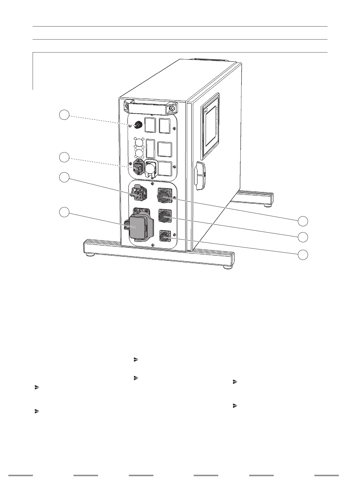
5.1.1 Conexión de FDE 100 L
1. Conecte el cable del circuito de protección
en la posición 4 y je el enchufe macho con
el cierre a presión.
2. Conecte el cable de la interfaz analógica en
la posición 5 y apriete la tuerca de unión.
3. Conecte el cable control de la unidad de
arrastre frontal en la posición 6 y apriete la
tuerca de unión.
4. Conecte el cable control del devanador
de hilo en la posición 7 y apriete la tuerca
de unión.
5. Conecte el cable de tensión de red en la
posición 3 y je el enchufe macho con el
cierre a presión.
Conexiones opcionales
Conecte la fuente de corriente de hilo
caliente DIX PI 270 HW con un cable de
bus CAN en la posición 1 y apriete la tuerca
de unión.
Conecte el cable de monitorización en la
posición 2.
5. Startup
5.1 Connecting the control unit
5.1.1 Connecting the FDE 100 L
1. Connect the protective circuit lead to item 4
and x the plug with the stirrup lock.
2. Connect the lead of the analog interface to
item 5 and tighten the cap nut.
3. Connect the control wire of the front drive
to item 6 and tighten the cap nut.
4. Connect the control wire of the wire feed to
item 7 and tighten the cap nut.
5. Connect the supply voltage lead to item 3
and x the plug with the stirrup lock.
Optional connections
Connect the hot wire power source
DIX PI 270 HW to a CAN-bus lead at
Pos. 1 and tighten the cap nut.
Connect the monitoring lead to item 2.
5. Inbetriebnahme
5.1 Steuerung anschließen
5.1.1 FDE 100 L anschließen
1. Schließen Sie die Schutzkreisleitung an
Pos. 4 an und xieren den Stecker mit dem
Spannbügel.
2. Schließen Sie die Leitung der analogen
Schnittstelle an Pos. 5 an und schrauben
die Überwurfmutter fest.
3. Schließen Sie die Steuerleitung des Front-
antriebs an Pos. 6 an und schrauben die
Überwurfmutter fest.
4. Schließen Sie die Steuerleitung des
Drahtvorschubs an Pos. 7 an und schrau-
ben die Überwurfmutter fest.
5. Schließen Sie die Netzspannungsleitung
an Pos. 3 an und xieren den Stecker mit
dem Spannbügel.
Optionale Anschlüsse
Schließen Sie die Heißdrahtstromquelle
DIX PI 270 HW mit einer CAN-Bus-Leitung
an Pos. 1 an und schrauben die Überwurf-
mutter fest.
Schließen Sie die Monitoring-Leitung an
Pos. 2 an.
SchweiSSen welding
weldingSoldadura SchweiSSen
39
:
:
:
:
:
:
1
5
3
4
7
6
2
 Loading...