EasyManua.ls Logo

Diode Dynamics Elite Series - User Manual

Default Icon
2 pages
Print Icon
To Next Page IconTo Next Page
Loading...
Elite Series 2018+ Ford Mustang
Combination Lamp Installation Guide
PAGE 4
(314) 205-3033 WWW.DIODEDYNAMICS.COM
WARRANTY
3 YEAR
PP0161C
DD5132 Ford Mustang 2018 Elite Foglamp White (set)
This installation guide is for the following SKUs:
Thank you for your purchase of Elite Series Combination Lamps for your
2018+ Mustang! Designed for perfect tment, these LEDs illuminate in a cool
white for your parking lights and DRL, and add a sequential turn signal as
well as a modern startup sequence any time the vehicle is unlocked.
Tools Needed: Plastic trim removal tool, 7mm socket, 8mm socket, 7/32” socket, 10mm
socket, and small screwdriver (included in kit)
PAGE 1
2. Using a plastic trim removal tool, remove the three
push rivets holding the inner fender liner in place.
Do this on both sides of the vehicle.
1. Using a plastic trim removal tool, remove the eight
push rivets on the upper valance. Then, gently pry
them o and remove the upper valance.
15. When desired aiming is reached, complete the install process by reversing steps one
through ve. First, secure the bumper cover to the core support and lower splash guard
using the original screws. Then reinstall the inner fender liner and upper valance using
the original push rivets.
12. While holding the bumper cover in front of the vehicle, plug in the fog lamp connectors
and place the bumper cover back onto the locators. Please note that the lower splash
guard should be on top of the chin spoiler.
13. Gently reinstall the push pins into each fender.
11. Using the integrated switch (located inside the
main connector on the back of the fog lamp housing)
select your desired turn signal blink rate.
• STAT: Static, non-sequential turn signal
• EU: Sequential, faster speed to match export
model blink rates
• US: Sequential, slower speed to match tail lights
Use the included small screwdriver to select desired
option. The factory connector will seal up this part
of the housing when installed.
14. Test function and aim fog lamps. To do so,
park 25 feet from a wall, on a at surface. The top
of the fog lamp beam pattern should be four inches
lower than the height of the lamp on your vehicle. To
adjust, locate the 8mm hex head bolt located on the
back of the fog lamp. Rotate this bolt clockwise to
aim downward, and counter-clockwise to aim
upward. Make sure to count the number
of rotations.
Please contact Diode Dynamics should you have any questions about the installation
or wiring process, at 314-205-3033 (10a-5p CST) or contact@diodedynamics.com.
EUSTAT US
DD5133 Ford Mustang 2018 Elite Foglamp Yellow (set)
25 feet
Top of
Beam
Level
Measure lamp height to center
Four
(
4
)
inches
NOTE: Do not rotate this bolt more than three full
turns in either direction. The lamps are factory-aimed
and should only require one rotation at most.
Question and Answer IconNeed help?

Do you have a question about the Diode Dynamics Elite Series and is the answer not in the manual?

Summary

Sequential Turn Signal Selection

Select Turn Signal Blink Rate

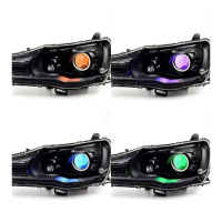
Choose between Static, EU Sequential, or US Sequential blink rates using the integrated switch.

Fog Lamp Installation and Aiming

Connect Fog Lamps and Reinstall Bumper

Plug in fog lamp connectors and place bumper cover back onto locators. Ensure splash guard is on top of chin spoiler.

Reinstall Push Pins

Gently reinstall the push pins into each fender after bumper cover placement.

Test and Aim Fog Lamps

Park 25 feet from a wall, adjust beam pattern by rotating 8mm hex bolt (max 3 turns).

Complete Installation

Reverse steps 1-5 to secure bumper cover, inner fender liner, and upper valance.

Bumper Cover Removal and Preparation

Remove Upper Valance

Use a plastic trim removal tool to remove eight push rivets on the upper valance.

Remove Inner Fender Liner

Use a plastic trim removal tool to remove three push rivets holding the inner fender liner.

Bumper Cover Removal and Component Installation

Remove Lower Splash Guard Screws

Use a 7mm socket to remove fifteen lower screws holding the bumper cover to the splash guard.

Remove Upper Bumper Cover Bolts

Use 8mm and 7/32" sockets to remove eight upper bolts securing the bumper cover to the core support.

Remove Fender Nuts and Push Pin

Use a 10mm socket to remove fender nuts, and disconnect the bumper cover by pulling forward.

Remove Bumper Cover

Lift and rotate bumper cover slightly upward to remove it. Disconnect factory fog lamp connectors.

Install DRL Harness

Unplug the factory headlight connector and install the new DRL harness.

Modify Fog Lamp Connector for DRL

Insert the DRL harness wire terminal into position 6 of the fog lamp connector.

Remove Factory Fog Lamps

Use a 7mm socket to remove three screws holding factory fog lamps to the bumper cover.

Install New Combination Lamps

Install new Elite Series lamps into factory positions and secure with factory 7mm screws.

Diode Dynamics Elite Series Specifications

General IconGeneral
BrandDiode Dynamics
ModelElite Series
CategoryAutomobile Accessories
LanguageEnglish

Related product manuals