9
Fig.G
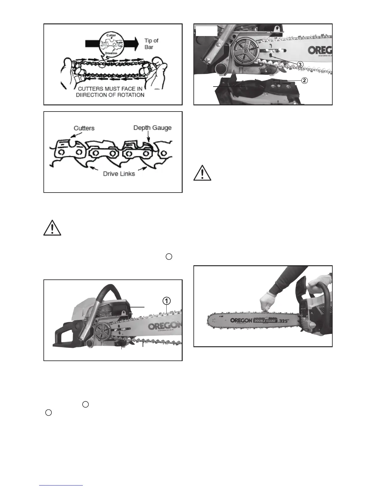
Fig.H
6) Lift the chain over and behind clutch retainer,
tting the drive links in the clutch drum sprocket.
CAUTION: Do not insert the chain
between the chain sprocket and the disc.
7) Fit bottom of drive links between the teeth in
the front nose sprocket of the guide bar.
8) Fit chain drives links into chain bar groove (
1
).
Place the chain (24) over the chain catcher (23)
on the bottom. (Fig I)
Fig.I
25
24
23
9) Pull chain bar forward until chain is snug in
chain bar groove. Ensure all drive links are in the
bar groove.
10) Now install clutch cover (22) making sure the
adjusting pin (
2
) is positioned in the lower hole
(
3
) in the chain bar. Remember this pin moves
the bar forward and backward as the screw is
turned. (Fig. J)
Fig.J
22
11) Install the chain bar locking nuts(8) and nger
tighten with Chain adjustment & Spark plug tool
(19) only. Tension the chain as detailed in the next
section.
2. CHAIN TENSION
WARNING! Wear protective
gloves when handling chain. The
chain is sharp and can cut you even
when it is not moving.
NOTE: When adjusting chain tension, make
sure the chain brake nuts are nger tight only.
Attempting to tension the chain when the chain
brake nuts are tight can cause damage.
Checking the tension:
Use the end of the Chain adjustment & Spark
plug tool (19) to move the chain(24) around guide
bar(12) (Fig. K).
Fig.K
If the chain is too tight, it will not rotate around the
guide bar.
If the chain is too loose, it will sag below the guide
bar.
Adjusting the tension (Fig. L):
Chain tension is very important. Chain stretch
occurs during use. This is especially true during
the rst few times you use your saw. Always
check chain tension each time you use and refuel
your saw.
1) Loosen chain bar locking nuts (8) until they are
nger tight against the clutch cover.
2) Turn chain adjusting screw (9) clockwise until
 Loading...