8
KNOW YOUR CHAIN SAW
“I”/”O” SWITCH (14)
The “I”/”O” switch is used to stop the engine.
THROTTLE TRIGGER (11)
The THROTTLE TRIGGER controls engine
speed.
THROTTLE LOCK--OFF (2)
The THROTTLE LOCK--OFF must be pressed
before you can squeeze the throttle trigger. This
feature prevents you from accidentally squeezing
the trigger.
CHOKE LEVER (10)
The choke and fast idle are set by pulling the
CHOKE LEVER out to the full extent for cold
starting or after refuelling. The choke provides
additional fuel to the engine during cold starting.
CHAIN BRAKE (6)
The chain brake is a device designed to stop
the chain if kickback occurs. The chain brake
activates automatically in the event of kickback.
The chain brake activates manually if the front
hand guard is pushed forward. The chain brake is
disengaged by pulling the front hand guard back
toward the front handle as far as possible.
CHAIN TENSION
It is normal for a new chain to stretch during the
rst 5 minutes of operation. Ensure the engine is
always SWITCHED OFF before tting or adjusting
the chain. You should check your chain tension
frequently. See CHAIN TENSION under the
ASSEMBLY section.
WARNING! Mufer is very hot during
and after use. Do not touch the mufer or
allow combustible material such as dry grass or
fuel to do so.
AS SE M BLY
WARNING! Protective gloves (not
provided) should be worn during assembly.
Never start the saw before having mounted or
regulated the chain.
1. MOUNTING THE GUIDE BAR AND
SAW CHAIN
WARNING! If received assembled,
repeat all steps to ensure your saw is
properly assembled and all fasteners are secure.
Always wear gloves when handling the chain. The
chain is sharp and can cut you even when it is not
moving!
Put the chain saw on a stable surface and carry
out the following steps for mounting the guide bar
and saw chain:
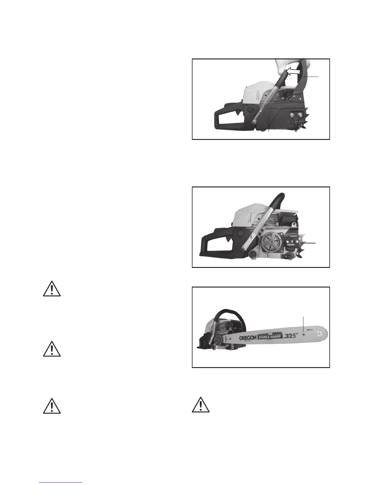
Release the chain brake (6) by pulling the hand
guard in direction of arrow. (Fig. D) Ensure the
chain brake lever is in disengaged position.
Fig.D
22
8
6
1) Unscrew the chain bar locking nuts(8) with
Chain adjustment & Spark plug tool (19).
2) Pull off the clutch cover (22).
3) Install the Spiked bumper (7) to the power unit.
(Fig. E)
Fig.E
7
4) Put on the guide bar (12). (Fig. F)
Fig.F
12
5) Carefully remove the chain from the package.
Hold chain with the drive links as shown. Check
the chain direction. (Fig. G & H)
WARNING! Cutters must face in
direction of rotation.
 Loading...