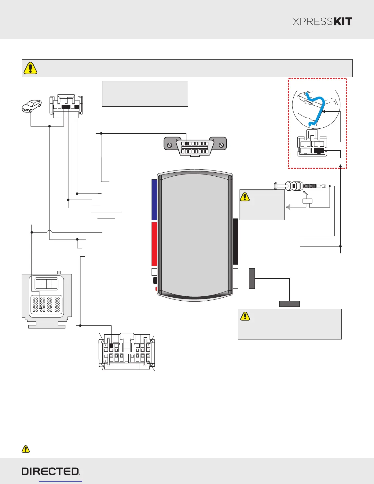
Wiring Diagram
Page 3
10
DBALL/
DBALL2
Prog. Button
LED
4
14 12 2
Green or Black
Connector located
at the ignition switch.
R. Code In (Car Side): Violet/Green: 8
J1850: Violet/Yellow: 2
Accessory Output: Yellow: 8
(+) 12V Input: Brown: 7
(+) 12V Input: Brown/Red: 12
(+) Ignition Output: Yellow/Red: 11
(+) 12V
J1850: Violet, pin 2
(+) 12V
Driver Door Trigger:
Gray/Black, pin A32
RF
Diagnostic connector
OBDII (connector side view)
1 8
169
The position of the R. Code wire may vary.
Test this wire using the following chart:
- 12V at Key Input - 4.3V at Ignition
- 0V at Accessory - 5V at Start
(-) RAP Off : Black/White: 1
R. Code Out (Car Side): Violet/Brown: 9
7: Pink/White: (+) Brake Input
Important!
The Hood Pin and Remote Start Safety Override Switch are mandatory safety devices, but are NOT supplied with the DBALL.
6: White/Black: (-) Hood Input
Hood Pin
Remote Start Safety
Override Switch
(+) 12V: Red: 13
(-) Ground: Black: 14
(+) 12V
(-) Ground
Brake Switch 2004-06
3
4
2
1
BCM
Black Connector
56-pin
B5
B8
B4
A48
A43
A1
A6
B1
OR
R. Code: White or White/Blue, pin 4
Key Side
BCM Side
6 5
4
3
2
1
(-) Parking Lights Output: Blue/Red: 12
With the exception of the OBDII Diagnostic connector, all adapters are displayed from the wire side (unless specified otherwise).
(-)Parking Lights: Brown/White, pin 2
You can connect to either a XL202
RFTD OR a SmartStart module.
Refer to the SmartStart/XL202
Installation Notes for more information.
(+) Ignition: pin 3
(+) Accessory: White/Red: pin 1
Driver Front Pillar
2011-12 (Canyon/H3)
Brake Sense:
Light Blue
1
6
14
7
Headlight Switch
Connector
The Remote
Start Safety
Override Switch
MUST be in the
OFF position.
Platform: DBALL/DBALL2
Firmware: GM5 Remote Start Ready (RSR) Installation
© 2015 Directed. All rights reserved.
Rev.: 20150626
Brake Switch 2004-06
3
4
2
1
Brake Switch 2007-10
Brake Sense:
Light Blue, pin 2
OR
Passenger
Kick Panel
4
1
3
2