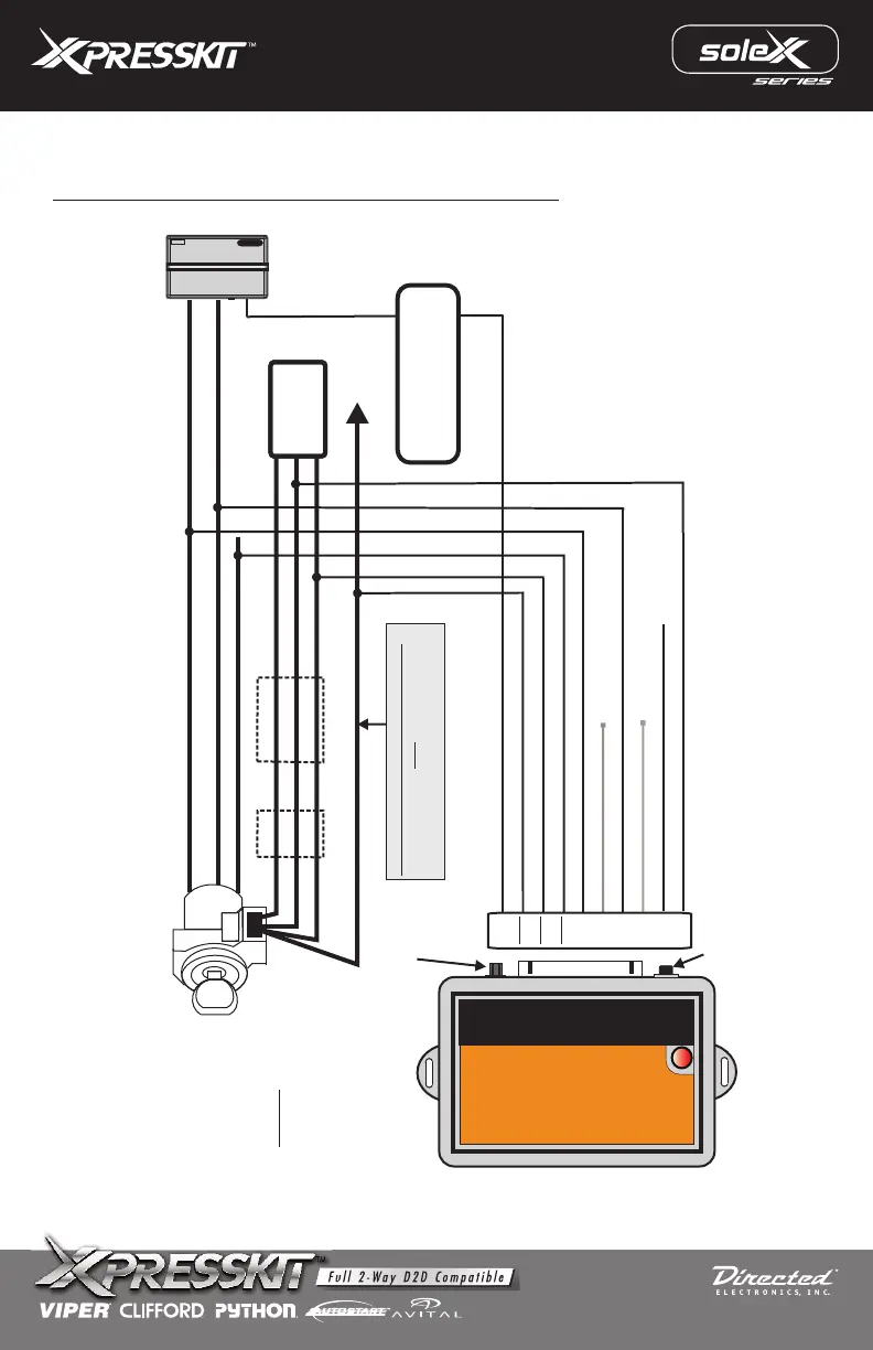
PASSLOCK 1 CONNECTION
OVERRIDE THE FOLLOWING GM PASSLOCK TYPES: PASSLOCK 1
White BlackWhite
Black BlackOR
Yellow Black
Connect to 12V Constant
Start Wire
Ground wire in Passlock harness
N/C
N/C
Ignition Wire
Passlock Resistor Value wire
Bulb Test Out
*Vehicle Key Sense wire*
(+)
N/C
(-)
(RV)
(+)
(-)
(-)
(-)
N/C
IGNITION KEY
KEY SENSE
Brown
Green
Blue
Violet/White
Violet
Pink/White
Pink
Orange
Red
Black
BULB TEST
STARTER
IGNITION
KEYSENSE WIRE CONNECTION
Connect this wire only if the vehicle’s
keysense wire goes to ground (Neg) when
the doors are closed & key is in the Ign.
(+)
INPUT
INPUT
INPUT
INPUT
OUTPUT
OUTPUT
OUTPUT
BCM
INPUT
Ground when running (status)
output from Remote Start
Programming
Jumper
Button
Programming
Passlock 1 Type
Once connected you must
select Passlock 1
Type BEFORE the
Passlock Resistor Code
can be programmed.
**
Connec
t
B
r
o
w
n w
i
re
ON
LY
a
ft
er
pr
ogramm
i
n
g
i
s c
o
m
ple
t
e
**
System
Remote Control
MODEL: pljx
Rev.: 20111017
© 2011 Directed Electronics. All rights reserved.