Do you have a question about the DIVERSITECH TYPHOON WX Series and is the answer not in the manual?
Manual uses symbols to highlight specific hazards. Be familiar with these symbols and accompanying text to avoid hazards.
Users must follow all applicable safety guidelines and regulations for safe use of fume and dust extraction equipment.
Identifies combustible dusts, chemical reaction hazards from combining dusts, and risks in environments with combustible dusts.
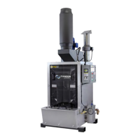
Provides visual diagrams and brief descriptions for WX 1200, WX 3000, WX 5000, and WX 6500 wet dust collectors.
Details water fill system, airflow, tank capacity, motor HP, phase, power requirements, and noise levels for each model.
Presents dimensional drawings (a, b, c, d) for the wet dust collectors, essential for space planning and installation.
Provides dimensions for collectors when fitted with an optional Downdraft Table, including connection and water level details.
Emphasizes avoiding flammables, checking electrical requirements, and ensuring the unit is properly grounded for safe operation.
Instructions for inspecting cartons for damage, removing packing material, handling the unit, and recording serial number information.
Guidelines for choosing a location near the operator and sufficiently close to a grounded power source for proper operation.
Details connecting water feed and overflow drain to suitable collection/drainage, and connection of water inlet and drain ports.
Guidance on duct diameter, length, material, and smooth bore ducting to optimize airflow resistance and performance.
Information on the auxiliary vent fan's function, exhaust requirements, and the importance of installing the backdraft damper.
Instructions for installing exhaust silencers on the exhaust collars of the blower housing using self-tapping screws.
Instructions for connecting power as outlined in Appendix 1, ensuring correct motor rotation and wiring for the auxiliary vent fan.
Step-by-step guide for unbolting panels, attaching the scroll, fastening the cone, and wiring the motor for the 15HP blower.
Ensures correct power sizing, performs function test by checking motor rotation, listening for smooth operation, and sensing suction.
Read and understand safety precautions, MSDS, and manufacturer instructions. Keep away from moving parts and check for spark arrestors.
Identifies key controls and indicators on the panel, including Alarm Annunciator, Stop, Start buttons, and PLC LCD display.
Explains how the wet filtration process captures dust, creates a humid environment, and the five basic components of the product.
Describes how the PLC controls the main motor, alarms, stop/start commands, and maintains water levels automatically.
Details how the ultrasonic sensor monitors water levels, triggers the fill valve, and activates low/high level alarms for safety.
Lists alarm conditions like motor overload, high temperature, low/high water level, and exhaust fan failure, which cause machine lockdown.
Provides a caution for adjustment and outlines steps for setting running water level, high limit, and low limit set points.
Emphasizes reading safety sections, disconnecting power, avoiding dust inhalation, keeping away from moving parts, and allowing parts to cool.
Lists essential personal protective equipment (PPE) and tools like eye protection, respirator, gloves, waste container, and sludge vac.
Details daily maintenance needs and provides step-by-step cleaning instructions for various components of the wet dust collector.
Flowchart guides users through diagnosing issues like motor operation, air flow restriction, and provides contact information for service.
Lists overload models and their corresponding Full Load Amperes (FLA) for different voltage and motor HP ratings.
Provides recommended fuse sizes for different electrical supply voltages used with the transformer.
Details the wiring and use of the 120 Vac relay for remote control functionality, including connection terminals.
Wiring diagram for the ultrasonic sensor, showing connections for +V, -V, and signal wires.
Step-by-step guide for manually setting the sensing window of the ultrasonic sensor using the setup button and object detection.
Explains that exhaust fans operate when the main blower is off, pushing air out, and how current sensors ensure proper operation.
Details HEPA installation following NFPA guidelines, temperature sensor placement, and the use of a photohelic meter for pressure monitoring.
2-year warranty against defects in material/workmanship. Limited to replacement parts, excludes misuse/improper installation.
Shipments are ex-plant; receiver is responsible for filing freight claims with the carrier for damages.
Requires RMA for returns. Material must be returned prepaid. Freight collect or no-RMA shipments will not be accepted.
| Filter Type | Cartridge Filter |
|---|---|
| Collection Capacity | 5 - 55 gallons (depending on model) |
| Inlet Diameter | 6 - 8 inches |
| Noise Level | 70 - 80 dB |
| Weight | 300 lbs |
| Dimensions | Varies by model |