http://www.diviotec.com
4
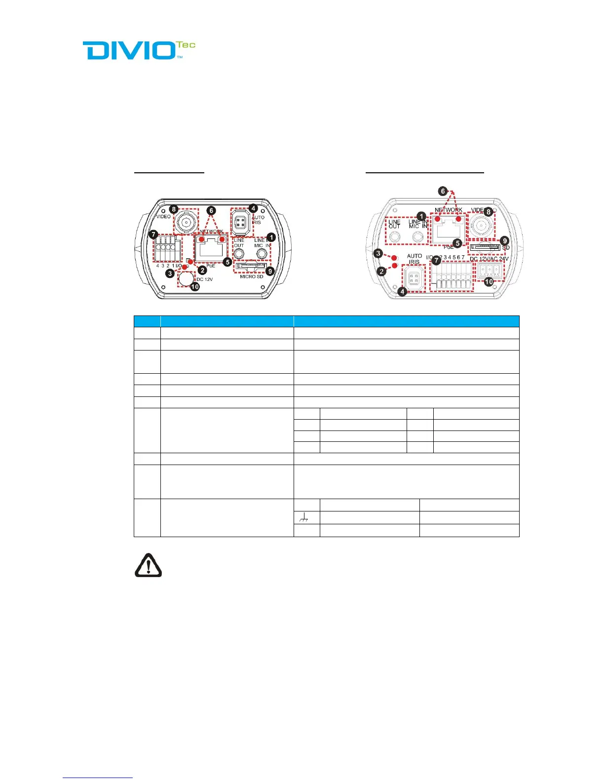
1.4 Connectors
The diagram below shows the IP Camera’s reset button and various connectors.
Definition for each connector will be given as follows.
DC 12V / PoE DC 12V / AC 24V / PoE
Two-way audio transmission
For power connection indication (green light)
3
Default Button
Press the button with a proper tool for at least 20
seconds to restore the system.
For auto iris lens connection
For network and PoE connections
For network connection and activity indication
7
Alarm I/O
1 Output+ 5 GND
2 Output- 6 D-
3 Input+ 7 D+
4 Input-
For analogue video output
9
microSD Card Slot
Insert the microSD card into the card slot to store
videos and snapshots. Do not remove the
microSD card when the camera is powered on.
10
Power (DC12V / AC 24V)
(AC 24V Model)
+
DC 12V AC 24V 1
DC 12V Reserved AC 24V GND
-
DC 12V GND AC 24V 2
NOTE: It is not recommended to record with the microSD card for 24/7
continuously, as it may not be able to support long term continuous data
read/write. Please contact the manufacturer of the microSD card for
information regarding the reliability and the life expectancy.