http://www.diviotec.com
5
2. Camera Cabling
Please follow the instructions below to complete IP camera installation.
2.1 Power Connection
Please refer to section Connectors. Alternatively, users can power up the
camera by PoE if a Power Sourcing Equipment (PSE) switch is available. Refer
to the section below for Ethernet cable connection.
NOTE: If PoE is used, make sure PSE is in used in the network.
2.2 Ethernet Cable Connection
To have best transmission quality, cable length shall not exceed 100 meters.
Connect one end of the Ethernet cable to the RJ-45 connector of the camera,
and the other end of the cable to the network switch or PC. The RJ-45 port
networks without routing to the outside plant.
NOTE: In some cases Ethernet crossover cable might be needed when
connecting the camera directly to the PC.
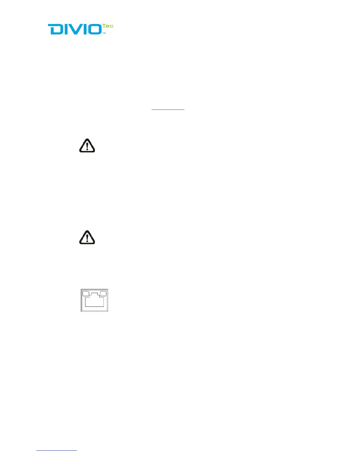
Check the status of the link indicator and the activity indicator LEDs. If the LEDs
are unlit, please check the LAN connection.
Green Link Light indicates good network connection.
Orange Activity Light flashes for network activity indication.