InstallatIon GuIde
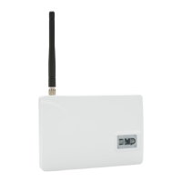
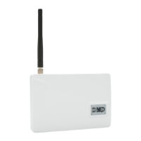
CellComRT Digital Cellular Communicator
Description
The CellComRT Digital Cellular Communicator provides a fully supervised alarm communication path over the GSM/
GPRS network. The CellComRT is installed remote from the panel enclosure in a supplied plastic housing and can be
powered directly from the XR100 or XR500 Series panel LX header or can be powered from an optional power supply.
What is Included
The CellComRT includes the following:
•
One Remote Cellular Communicator
• One380-400SecureComWirelessSIMCard
• PlasticHousing
• One383RubberDuckAntenna
• OneCELLCOMBATLithiumPolymerRechargeableBattery
Compatibility
The CellComRT is compatible with the XR100, XR100N, XR500,
XR500NandXR500ECommandProcessorsusingsoftwareVersion
203orhigher.TheCellComRToperatesonthepanelLXheader
andcanbeusedwithan1100SeriesWirelessReceiver.
Installation Safety
Ground Yourself Before Handling the Panel! To discharge
static, touch any grounded metal, such as the enclosure,
before touching the panel.
Remove All Power From the Panel! RemoveallACandBatterypowerfromthepanelbeforeinstallingorconnecting
any modules, cards, or wires to the panel.
Bus Connection
TheCellComRTinterfaceswiththeXR100/XR500Seriesusingthepanel’son-boardLX-Busheader(J22).
The
CellComRTcanbemountedupto100feetfromthepanelenclosureusing22AWGwireor250feetusing18AWG
wire.
Harness Connection
Use the following steps to connect the CellComRT to the panel:
1.Installajumperacrosstheheaderpinsnexttotheletter“X”ontheXR100/XR500panel’sJ23header.
2.
Connectthe4-wireharnessfromtheJ22headerontheCellComRTtotheXR100/XR500panel’sLX-Busheader(J22).
3.Afterpower-upoftheCellComRT,brieyresettheXR100/XR500panelusingtheJ16jumpertoactivate
operation.
Installing the CellComRT
Connecting Backup Rechargeable Battery
Observepolarityandconnecttherechargeablebatteryleadconnectortothe2-pinCellComJ4
battery header.
Tamper Switches
The CellComRT is equipped with two tamper switches. One is located inside the housing. The
second tamper is a wall tamper switch.
BeforemountingtheCellComRTunit,followthesesteps
to install the tamper springs:
1.
Place the included tamper springs on the tamper switches. The long tamper spring installs
inside the housing and the short tamper spring installs in the opening in the back of the
CellComRT housing.
2.Withspringinplace,mounttheCellComRTonaatsurfacethatengagesthetamper
spring and closes the tamper.
See Figure 1 for mounting hole locations.
Connecting the Antenna to the CellComRT
AttachtheRubberDuckAntennatotheAntennaSMAConnector(J19)locatedonthetopright
side of the CellComRT. See Figure 2.
CellComRT
Mounting Holes
Antenna
Tamper
Switch
S2
J19
Battery
Transmit LED
J4
SIM Card
Holder
J22
Mounting Screw
Shoulder Washer
Figure 1: CellComRT PCB
Antenna
J19
Battery
Charge LED
Transmit LED
J16 Reset
J22
CellCom
J4
J25
SIM Card
Holder
J5
Rubber Duck
Antenna
Figure 2: CellComRT
Antenna Installation